
How to Select Materials for Thermal Cycling in Space Applications
There is no single “perfect” material for thermal cycling in space.
A titanium alloy may provide an attractive strength-to-weight ratio and lower thermal expansion than aluminum, but it also has relatively low thermal conductivity and can create machining or galling challenges.
A nickel-based superalloy may retain strength at elevated temperature, but its density, cost, machinability, and thermal expansion may make it unnecessary for a moderate-temperature satellite structure.
An aluminum alloy may conduct heat efficiently and reduce mass, but its higher coefficient of thermal expansion can create alignment or interface problems in precision assemblies.
The most suitable material is therefore not the alloy with the highest temperature rating, greatest strength, or lowest coefficient of thermal expansion. It is the material and process system that best match the component’s thermal profile, structural constraints, interfaces, surface condition, verification plan, and mission risk.
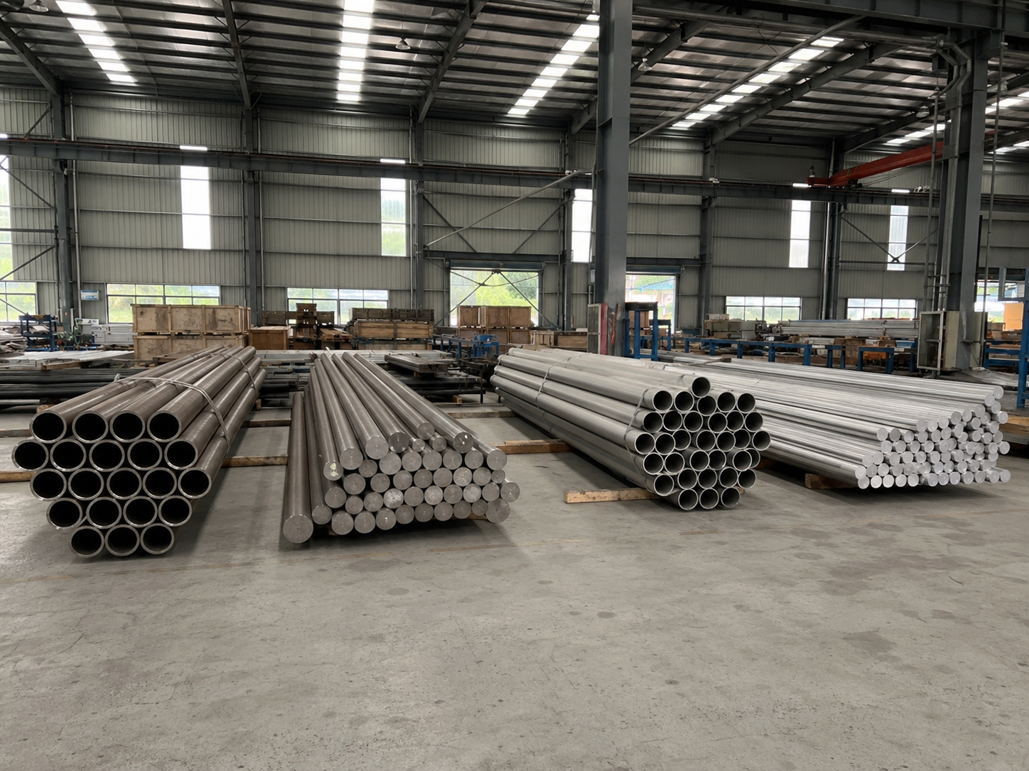
Material selection should begin with a clear understanding of what thermal cycling actually does to a component.
What Does Thermal Cycling Actually Do to a Material?
When temperature changes, a material normally expands or contracts.
For a simple unconstrained component, the approximate dimensional change can be expressed as:
ΔL = α × L × ΔT
Where:
- ΔL is the change in length;
- α is the coefficient of thermal expansion;
- L is the original length;
- ΔT is the temperature change.
This equation helps estimate dimensional movement. It does not, by itself, predict cracking or fatigue.
If a component can expand and contract freely, the temperature change may produce dimensional movement without creating high internal stress.
Significant thermal stress is more likely when:
- Expansion is mechanically constrained;
- Two connected materials have different CTE values;
- One side of the component heats faster than the other;
- A coating expands differently from its substrate;
- A fastener or joint prevents free movement;
- Residual stress already exists from machining, forming, welding, or heat treatment;
- Repeated cycles create local plastic strain;
- A sharp corner, hole, thread, notch, or weld concentrates stress.
This distinction is important because thermal cycling is not automatically thermal fatigue.
Thermal fatigue develops when repeated temperature changes produce repeated local stress or strain that is large enough to initiate and grow damage.
Thermal-Cycling Damage Mechanisms
| Mechanism | How It Develops | Possible Result |
|---|---|---|
| Free thermal expansion | Component changes size without significant constraint | Reversible dimensional movement |
| CTE mismatch | Connected materials expand by different amounts | Interface stress, joint slip, distortion |
| Thermal gradient | Different parts of the component reach different temperatures | Bending, warping, local stress |
| Constrained expansion | Mounts, fasteners, welds, or adjacent parts restrict movement | Thermal stress and possible yielding |
| Thermal fatigue | Repeated thermal stress or strain accumulates | Crack initiation and growth |
| Preload change | Fasteners and joined materials expand differently | Joint loosening or excessive clamp load |
| Coating mismatch | Coating and substrate have different thermal response | Cracking, delamination, property change |
| Seal mismatch | Seal and housing contract differently | Leakage or loss of contact |
| Creep or stress relaxation | Sustained stress acts at sufficiently high temperature | Permanent deformation or preload loss |
| Microstructural instability | Long exposure or cycling changes phases or precipitates | Property drift or reduced strength |
The first selection question should not be:
“Which material survives the widest temperature range?”
It should be:
“Where will thermal strain be constrained or concentrated in this particular component?”
Why CTE Alone Is Not Enough
Coefficient of thermal expansion is one of the most important space-material properties, but it is only one part of the thermal response.
ASTM E228 thermal expansion testing and ASTM E289 thermal expansion testing provide methods for measuring linear thermal expansion.
However, a single room-temperature CTE number can still be misleading.
CTE may vary with:
- Temperature;
- Material direction;
- Heat treatment;
- Microstructure;
- Product form;
- Composite layup;
- Phase transformations;
- Measurement method.
The engineering team also needs to understand what the material is connected to and how heat moves through the assembly.
Properties That Must Be Reviewed Together
| Property | Why It Matters During Thermal Cycling |
|---|---|
| CTE | Determines dimensional expansion and contraction |
| Elastic modulus | Influences stress generated when expansion is constrained |
| Yield strength over temperature | Determines whether local thermal stress causes permanent deformation |
| Fatigue behavior | Influences resistance to repeated cyclic strain |
| Fracture toughness | Influences tolerance to cracks and defects |
| Thermal conductivity | Controls temperature gradients within the part |
| Thermal diffusivity | Influences how quickly the material responds to temperature changes |
| Specific heat | Influences the energy needed to change component temperature |
| Creep resistance | Relevant under sustained stress at sufficiently high temperature |
| Stress-relaxation behavior | Important for fasteners, springs, clamps, and preload-sensitive joints |
| Solar absorptance | Influences absorbed solar energy |
| Infrared emittance | Influences heat rejection by radiation |
| Density | Affects launch mass and structural design |
| Surface condition | Influences optical, thermal, fatigue, and contamination behavior |
A low-CTE material is not automatically dimensionally stable if it has poor thermal conductivity and develops large temperature gradients.
A high-conductivity material can reduce gradients but may still undergo large total expansion if its CTE is high.
The right answer depends on the complete assembly.
Define the Mission Thermal Profile Before Comparing Alloys
“Space temperature” is not one fixed range.
The component temperature depends on:
- Orbit;
- Orientation;
- Sunlight and eclipse duration;
- Internal heat generation;
- Surface absorptance and emittance;
- Conductive heat paths;
- Radiator and insulation design;
- Nearby equipment;
- Operational mode;
- Mission phase;
- Thermal-control strategy.
The material supplier should not invent a universal space temperature range.
The project should define the expected thermal profile.
Mission Thermal Information to Confirm
| Requirement | Question to Answer |
|---|---|
| Minimum temperature | What is the coldest predicted component temperature? |
| Maximum temperature | What is the hottest predicted component temperature? |
| Qualification temperature | What test margin is required by the project? |
| Number of cycles | How many hot-to-cold transitions are expected? |
| Cycle rate | How quickly will temperature change? |
| Dwell time | How long will the part remain at each extreme? |
| Thermal gradient | Will all sections reach the same temperature? |
| Mechanical load | Is the component loaded while temperature changes? |
| Constraint | Can it expand freely, or is movement restricted? |
| Interface materials | Which materials are bolted, bonded, coated, welded, or brazed together? |
| Vacuum level | Will the cycling occur in vacuum, gas, or atmosphere? |
| Surface state | What coating, finish, oxidation state, or contamination condition applies? |
| Mission duration | Could long-term exposure change material or surface properties? |
| Verification level | Is this a coupon, component, assembly, qualification, or flight test? |
ECSS materials and processes selection links material and process selection directly to mission performance requirements.
That principle is more useful than trying to select a material from a generic “space alloy” ranking.
Why Standard Datasheets Are Only a Starting Point
A standard material datasheet usually provides:
- Typical chemical composition;
- Room-temperature tensile strength;
- Yield strength;
- Elongation;
- Hardness;
- Density;
- A general CTE value;
- General corrosion or oxidation information.
This information is useful for early screening.
It does not normally establish performance under a mission-specific combination of thermal cycling, vacuum, constraint, radiation, vibration, joint design, surface treatment, and duration.
Datasheet Information vs. Mission Evidence
| Generic Datasheet Information | Additional Mission-Relevant Evidence |
|---|---|
| One CTE value | CTE over the actual temperature range |
| Room-temperature tensile strength | Strength and modulus at hot and cold limits |
| General fatigue data | Fatigue data for relevant surface, condition, temperature, and load ratio |
| General corrosion resistance | Exposure-specific environmental compatibility |
| Melting point | Creep, stress relaxation, oxidation, and stability below melting |
| Typical thermal conductivity | Conductivity or diffusivity over the operating range |
| Generic surface condition | Actual coating, polishing, oxide, or finish condition |
| General alloy designation | Exact product standard, heat treatment, product form, and batch |
| Typical material properties | Heat-specific MTR and required qualification data |
| Supplier marketing statement | Defined test method, specimen, environment, and acceptance criteria |
A data point is useful only when the following are understood:
- What material condition was tested?
- What specimen geometry was used?
- What temperature range was tested?
- Was the test performed in air, inert gas, or vacuum?
- Was the specimen mechanically constrained?
- Was the surface polished, machined, coated, or oxidized?
- How many cycles were performed?
- What failure or acceptance criterion was used?
- Does the test represent the final component?
- Is the data typical, minimum, heat-specific, or qualification-based?
How Vacuum Changes the Thermal Problem
Vacuum does not automatically damage a metallic alloy.
Its most direct thermal effect is that convection is greatly reduced or absent. Heat transfer is therefore dominated by:
- Conduction through joints, fasteners, supports, harnesses, and thermal straps;
- Radiation between surfaces and the surrounding environment;
- Internal heat generation.
This makes surface thermo-optical properties and conductive interfaces especially important.
ECSS thermo-optical property testing defines methods for evaluating solar absorptance and infrared emittance of thermal-control materials.
A polished metal surface, anodized surface, painted surface, oxidized surface, coated surface, and contaminated surface can reach different temperatures even when the underlying alloy is the same.
Vacuum-Related Questions
- What surface coating or finish is present?
- What are the solar absorptance and infrared emittance?
- Will these properties change with contamination or radiation?
- How will heat enter and leave the component?
- What is the thermal contact conductance at bolted joints?
- Are thermal interface materials used?
- Will lubricants, adhesives, seals, or polymers outgas?
- Is bake-out required?
- Will thermal cycling change joint contact or preload?
- Is a system-level thermal-vacuum test required?
The NASA Outgassing Database provides ASTM E595-based screening data for vacuum outgassing.
However, an outgassing result does not prove thermal-cycling life.
Likewise, a metallic MTR does not prove the outgassing performance of a finished assembly containing adhesives, coatings, seals, lubricants, cables, labels, or trapped volumes.
Thermal Cycling, Launch Loads, and Mechanical Fatigue
A spacecraft component must normally survive launch before experiencing long-term orbital thermal cycles.
Launch environments can include:
- Static acceleration;
- Random vibration;
- Acoustic excitation;
- Mechanical shock;
- Fastener preload changes;
- Local resonance;
- Interface movement.
NASA environmental verification guidance treats thermal-vacuum cycling, random vibration, acoustic testing, and mechanical shock as separate verification areas.
These environments may interact through accumulated damage, but they should not be treated as one generic “space fatigue” value.
Combined Damage Questions
| Question | Why It Matters |
|---|---|
| Is thermal cycling performed before or after vibration testing? | Test order can reveal workmanship or accumulated-damage issues |
| Is the component preloaded? | Thermal cycling may change clamp load |
| Are joints susceptible to slip or fretting? | Vibration and CTE mismatch can interact |
| Are there threads, holes, or sharp radii? | These create local stress concentration |
| Is the component already stressed during thermal cycling? | Mean stress changes fatigue behavior |
| Does machining leave tensile residual stress? | It may influence crack initiation |
| Are coatings or platings present? | Cracks may initiate at surface or interface defects |
| Is fracture control required? | Defect acceptance and NDT may need to be defined |
ECSS mechanical testing of space metals addresses tensile, fatigue, and fracture testing for metallic materials used in spacecraft hardware.
A room-temperature tensile result cannot substitute for component-level fatigue or thermal-cycle verification.
Radiation Is Mission-Specific
Radiation should not be added mechanically to every thermal-cycling material comparison.
The relevant environment depends on:
- Orbit;
- Mission duration;
- Shielding;
- Solar activity;
- Particle type;
- Particle energy;
- Total ionizing dose;
- Displacement damage;
- Component temperature;
- Surface exposure.
ECSS radiation testing for space materials defines procedures for electromagnetic radiation and charged-particle testing of spacecraft materials.
For many conventional metallic structural components, radiation may not be the dominant thermal-cycling risk.
Radiation may be more important for:
- Polymers;
- Adhesives;
- Coatings;
- Optical surfaces;
- Thermal-control finishes;
- Electronic materials;
- Certain composites;
- Specialized high-dose missions.
A supplier should not describe titanium or nickel alloy as “radiation resistant” without defining:
- Radiation type;
- Dose or fluence;
- Temperature;
- Exposure time;
- Property being evaluated;
- Acceptance criterion.
Atomic Oxygen Is Mainly an Exposure-Specific LEO Issue
Atomic oxygen is strongly associated with exposed surfaces in low Earth orbit.
NASA’s atomic oxygen durability guidance focuses particularly on polymer erosion during long-duration LEO exposure.
This does not mean metals and coatings are irrelevant. Surface oxides, coatings, optical properties, electrical behavior, and contamination may still need evaluation.
The correct questions are:
- Is the spacecraft operating in LEO?
- Is the component directly exposed?
- Is the surface coated?
- Could the coating crack under thermal cycling?
- Could atomic oxygen change absorptance or emittance?
- Is coupon exposure or accelerated testing required?
A component inside a sealed enclosure or a deep-space instrument should not be selected primarily for atomic-oxygen resistance unless the mission environment requires it.
How Different Material Families Respond to Thermal-Cycling Requirements
No material family is universally superior.
Aluminum Alloys
Potential advantages:
- Low density;
- High thermal conductivity;
- Mature aerospace manufacturing;
- Good machinability;
- Useful for panels, housings, frames, and thermal structures.
Important limitations:
- Relatively high CTE;
- Strength may decrease at elevated temperature;
- Surface treatment influences thermo-optical behavior;
- Thread and wear resistance may require inserts or coatings;
- Galvanic interfaces need control.
Aluminum may be highly effective when mass and heat spreading dominate, even though its CTE is higher than titanium or low-expansion alloys.
Titanium Alloys
Potential advantages:
- High strength-to-weight ratio;
- Lower CTE than many aluminum alloys;
- Corrosion resistance;
- Useful for brackets, fittings, fasteners, and concentrated load paths.
Important limitations:
- Relatively low thermal conductivity;
- Galling at sliding or threaded interfaces;
- Machining and residual-stress considerations;
- Higher cost than common aluminum alloys;
- Surface and joining requirements;
- Grade and heat-treatment dependence.
Ti-6Al-4V may be considered for selected structural interfaces, but it is not automatically the best material for thermally stable optical structures or heat-spreading components.
For a more application-specific discussion, see titanium alloy bars for satellite structural components.
Nickel-Based Superalloys
Potential advantages:
- Elevated-temperature strength;
- Creep and stress-relaxation capability in appropriate grades;
- Oxidation or corrosion resistance;
- Stability in selected propulsion and high-temperature applications.
Important limitations:
- High density;
- High cost;
- Difficult machining;
- Long lead time for specialized grades;
- Thermal expansion may remain significant;
- High-temperature performance may be unnecessary for moderate-temperature spacecraft structures.
Alloy 718 or other nickel-based superalloys may be valuable for propulsion or high-temperature loaded components. They are not automatically better for ordinary satellite brackets or optical supports.
Austenitic Stainless Steels
Potential advantages:
- Established fabrication and welding routes;
- Good low-temperature toughness in many austenitic grades;
- Mechanical stability;
- Broad availability;
- Experience in vacuum equipment.
Important limitations:
- Higher density than aluminum and titanium;
- CTE can be relatively high;
- Thermal conductivity is moderate;
- Magnetic permeability can change after forming or welding;
- Corrosion requirements remain environment-specific.
Low-Expansion Iron-Nickel Alloys
Potential advantages:
- Low CTE within defined temperature ranges;
- Useful for selected precision, optical, and sealing applications.
Important limitations:
- High density;
- Magnetic behavior;
- Lower corrosion resistance than some stainless or nickel alloys;
- Low thermal conductivity;
- CTE advantage is temperature-range dependent;
- Machining and joining must be controlled.
Invar-type materials should not be selected solely because they have a low room-temperature CTE.
Copper and Copper Alloys
Potential advantages:
- High thermal conductivity;
- Useful for thermal straps, heat spreaders, electrical paths, and selected seals.
Important limitations:
- High density;
- Lower strength in some conditions;
- Surface oxidation and contamination;
- Softness and deformation;
- Joining and interface considerations.
Composites and Ceramics
Potential advantages:
- Tailorable CTE;
- Low mass;
- High stiffness-to-weight ratio;
- High-temperature or electrically insulating capability in selected systems.
Important limitations:
- Anisotropy;
- Brittle failure in some ceramics;
- Moisture history and outgassing;
- joining complexity;
- microcracking;
- coating and interface qualification;
- limited repairability.
Material-Family Comparison
| Material Family | Thermal-Cycling Advantage | Main Trade-Off |
|---|---|---|
| Aluminum alloys | Heat spreading and low mass | Higher CTE |
| Titanium alloys | Strength-to-weight and moderate CTE | Low conductivity and galling |
| Nickel superalloys | High-temperature strength and creep resistance | Density, cost, machining |
| Austenitic stainless steels | Stability, weldability, vacuum experience | Density and CTE |
| Invar-type alloys | Low CTE in defined ranges | Density, magnetism, low conductivity |
| Copper alloys | High thermal conductivity | Density and lower structural efficiency |
| Carbon composites | Tailorable CTE and stiffness | Anisotropy, joining, qualification |
| Ceramics | Low CTE or high-temperature stability in selected grades | Brittleness and joining |
Select the Material by Component Function
Primary or Secondary Structural Bracket
Important properties:
- Strength-to-weight ratio;
- Stiffness;
- launch fatigue;
- CTE relative to mounted equipment;
- fastener preload;
- machining stability;
- fracture requirement.
Possible materials:
- Aluminum;
- titanium;
- stainless steel;
- composite or hybrid structures.
Optical or Sensor Mount
Important properties:
- Dimensional stability;
- CTE;
- thermal conductivity;
- thermal gradient;
- stiffness;
- residual stress;
- alignment retention.
Possible materials:
- Aluminum;
- titanium;
- Invar-type alloys;
- composites;
- ceramic or hybrid systems.
The strongest material is rarely the automatic best choice.
Thermal Strap or Heat Spreader
Important properties:
- Thermal conductivity;
- flexibility;
- mass;
- joint conductance;
- electrical requirements.
Possible materials:
- Copper;
- aluminum;
- engineered flexible thermal materials.
Nickel superalloy would normally add mass without solving the dominant problem.
Fastener or Insert
Important properties:
- Preload retention;
- CTE mismatch;
- galling;
- fatigue;
- galvanic compatibility;
- coating and lubrication.
Possible materials:
- Titanium;
- stainless steel;
- nickel alloy;
- application-specific fastener materials.
Propulsion or High-Temperature Component
Important properties:
- Strength at temperature;
- creep;
- stress relaxation;
- oxidation;
- thermal fatigue;
- fluid compatibility.
Possible materials:
- Nickel superalloys;
- titanium alloys within verified temperature limits;
- refractory alloys;
- specialized stainless alloys.
Cryogenic Support
Important properties:
- Low-temperature toughness;
- thermal contraction;
- conductivity;
- heat leak;
- joint compatibility;
- fracture behavior.
Possible materials:
- Austenitic stainless steel;
- titanium;
- aluminum;
- composites;
- application-specific low-conductivity supports.
How Should Thermal-Cycling Tests Be Specified?
A request such as “perform thermal cycling” is incomplete.
ECSS thermal cycling testing under vacuum establishes a framework for specifying, executing, and reporting thermal-cycle testing under vacuum for spacecraft materials, processes, parts, and assemblies.
A useful test specification should define:
| Test Parameter | Information to Define |
|---|---|
| Test article | Coupon, raw material, component, assembly, or complete unit |
| Material condition | Grade, heat treatment, surface, coating, and manufacturing route |
| Hot temperature | Target, tolerance, and qualification margin |
| Cold temperature | Target, tolerance, and qualification margin |
| Number of cycles | Based on qualification or acceptance objective |
| Ramp rate | Controlled transition or natural response |
| Dwell time | Time at each extreme and stabilization criterion |
| Vacuum level | Pressure requirement during cycling |
| Mechanical constraint | Free, mounted, bolted, loaded, or flight-like configuration |
| Instrumentation | Thermocouple locations, displacement, strain, pressure, or electrical monitoring |
| Operational state | Powered, unpowered, or mixed modes |
| Inspection points | Before, during, and after test |
| Acceptance criteria | Cracks, deformation, leakage, resistance, alignment, coating, or functional limits |
| Failure review | Procedure for anomalies and retesting |
| Report content | Actual profile, deviations, observations, measurements, and disposition |
The number of cycles should not be copied blindly from another mission.
The required test depends on:
- Qualification philosophy;
- hardware level;
- expected mission cycles;
- design margin;
- process maturity;
- component criticality;
- customer or agency requirements.
Coupon Testing, Component Testing, and System Testing Are Not Equivalent
Material Coupon Test
Useful for:
- Comparing alloys;
- checking CTE;
- evaluating coating adhesion;
- measuring basic thermal fatigue;
- screening surface treatments.
Limitations:
- Does not represent full geometry;
- joints and fasteners are absent;
- thermal gradients may differ;
- manufacturing residual stress may not be represented.
Component Test
Useful for:
- Evaluating real geometry;
- monitoring distortion;
- checking interfaces;
- assessing seals, welds, threads, and coatings.
Limitations:
- May not reproduce complete spacecraft thermal boundaries;
- mounting configuration must be representative.
Assembly or Unit Thermal-Vacuum Test
Useful for:
- Functional verification;
- interface behavior;
- integrated thermal paths;
- workmanship screening;
- contamination and operational checks.
Limitations:
- May not isolate the cause of a material-level issue;
- expensive and difficult to repeat.
A successful coupon test does not automatically qualify a complete assembly.
A successful unit test also does not prove that every raw material property is ideal; it proves that the tested configuration met the specified acceptance criteria.
How to Review Supplier Test Data
Supplier data should be classified before it is used.
Types of Supplier Data
| Data Type | What It Means |
|---|---|
| Typical datasheet value | General reference based on representative material |
| Minimum specification value | Required lower or upper limit under a product standard |
| MTR value | Actual result associated with a specific heat or batch |
| Qualification data | Evidence generated for a defined material, process, or product configuration |
| Design allowable | Statistically derived value approved for design use |
| Literature value | Published result that may not match the purchased material |
| Customer-specific test | Result generated under project-defined conditions |
| Component test result | Performance of a defined geometry and assembly |
Before using a value, ask:
- Is it typical, minimum, heat-specific, or statistically derived?
- Does it apply to the same alloy grade?
- Does it apply to the same heat treatment?
- Does it apply to the same product form and section size?
- Does it cover the same temperature range?
- Was the surface condition representative?
- Was the material tested in air or vacuum?
- Was the specimen constrained?
- Does the orientation match the component?
- Is the test method inside the laboratory’s accredited scope?
What Does an MTR Prove?
An MTR or MTC may provide:
- Alloy grade;
- Heat number;
- Chemical composition;
- Room-temperature mechanical properties;
- Heat-treatment condition;
- Product specification;
- Product form;
- Selected inspection results.
It normally does not prove:
- Thermal-cycle life;
- Dimensional stability of the final part;
- CTE over the full mission range;
- Coating durability;
- Thermo-optical stability;
- Vacuum compatibility of the complete assembly;
- Fatigue life of a machined component;
- radiation resistance;
- Atomic-oxygen durability;
- Mission success.
BS EN 10204 inspection documents can be used to define inspection-document types for metallic products.
For a broader explanation, see technical documents aerospace material buyers should request.
What Additional Documents May Be Needed?
| Requirement | Possible Supporting Document |
|---|---|
| Material identity | MTR/MTC, CoC, PMI, heat traceability |
| CTE | ASTM E228 or E289 report |
| Thermal conductivity or diffusivity | Applicable thermophysical-property report |
| Thermo-optical behavior | Absorptance and emittance report |
| Mechanical properties over temperature | Hot or cold tensile test report |
| Fatigue or fracture | Relevant fatigue, crack-growth, or fracture report |
| Microstructure | Grain, phase, macrostructure, or metallographic report |
| Internal integrity | UT or other NDT report |
| Surface condition | Roughness, PT, visual, coating, or finish report |
| Thermal cycling | Defined thermal-cycle test report |
| Thermal vacuum | Component or unit thermal-vacuum report |
| Outgassing | ASTM E595 or project-specific report |
| Radiation | Mission-specific radiation test report |
| Atomic oxygen | LEO exposure or coating qualification evidence |
| Quality system | AS9100 or contractually required QMS certificate |
| Critical process | Nadcap or customer-approved process evidence |
| Laboratory competence | ISO/IEC 17025 certificate and relevant scope |
Not every order requires every document.
The correct documentation package should match the hardware level and the acceptance risk.
How to Evaluate Supplier Quality Claims
AS9100 aerospace quality management supports aerospace quality-management system controls.
Nadcap critical process accreditation applies to defined critical processes such as heat treating, chemical processing, NDT, and materials testing.
ISO/IEC 17025 laboratory competence applies to testing and calibration laboratories.
These documents serve different purposes.
- AS9100 does not prove the chemistry of a specific heat.
- Nadcap heat-treatment accreditation does not prove that NDT is accredited.
- ISO/IEC 17025 accreditation does not mean every test method is inside the laboratory scope.
- An MTR does not prove mission-level thermal-cycle performance.
Supplier Questions That Reveal Real Capability
- What exact alloy, product form, standard, and revision are offered?
- What heat-treatment condition is supplied?
- Is the property data typical, minimum, or heat-specific?
- What temperature range was used for CTE testing?
- Can thermal conductivity or diffusivity data be provided?
- Are absorptance and emittance values based on the actual surface finish?
- What manufacturing processes are performed internally?
- Which processes are subcontracted?
- Can the original heat be traced to every delivered piece?
- Can the supplier provide microstructure data when required?
- What NDT method and acceptance level are available?
- Can hot or low-temperature mechanical testing be arranged?
- Can thermal-cycle testing be performed in vacuum?
- What fixtures and constraints are used during testing?
- Does the test reproduce the actual component interface?
- What laboratory performs the testing?
- Is the required method included in its ISO/IEC 17025 scope?
- Does any Nadcap accreditation cover the actual facility and process?
- How are process changes and substitutions controlled?
- How are nonconforming results handled?
- Can the same material and process route be repeated later?
- What records will be supplied before shipment?
- How long will the records be retained?
- Who is responsible for final engineering suitability approval?
A supplier should clearly distinguish between:
- What it manufactures;
- What it outsources;
- What its MTR proves;
- What third-party testing proves;
- What still requires customer engineering validation.
A Better Risk-Based Selection Process
Step 1: Define the Component Function
Determine whether the part is:
- Structural;
- Optical;
- Thermal;
- Mechanical;
- Sealing;
- Electrical;
- Fluid-related;
- High-temperature;
- Cryogenic;
- Contamination-sensitive.
Step 2: Define the Full Thermal Profile
Document:
- Minimum and maximum temperature;
- Rate of temperature change;
- Number of cycles;
- Dwell time;
- thermal gradients;
- vacuum level;
- surface exposure.
Step 3: Identify Constraints and Interfaces
Review:
- Fasteners;
- welds;
- brazed joints;
- adhesive bonds;
- coatings;
- seals;
- composite interfaces;
- dissimilar metals;
- mounting stiffness.
Step 4: Identify the Governing Failure Mode
Possible governing risks include:
- Excessive distortion;
- thermal fatigue;
- preload loss;
- coating delamination;
- seal leakage;
- crack growth;
- creep;
- stress relaxation;
- alignment drift;
- galling;
- contamination.
Step 5: Screen Material Families
Compare:
- Aluminum;
- titanium;
- nickel alloys;
- stainless steel;
- copper;
- low-expansion alloys;
- composites;
- ceramics.
Step 6: Confirm Manufacturing Feasibility
Review:
- Availability;
- product form;
- machining;
- welding;
- coating;
- heat treatment;
- NDT;
- section size;
- lead time.
Step 7: Define the Evidence Package
Specify:
- Product standard;
- MTR;
- CTE data;
- surface data;
- mechanical tests;
- NDT;
- thermal cycling;
- laboratory requirements;
- traceability.
Step 8: Validate at the Correct Hardware Level
Do not rely only on coupon data when the dominant risks are in:
- joints;
- fasteners;
- welds;
- coatings;
- seals;
- interfaces;
- complete assembly geometry.
Risk-Based Hardware Matrix
| Hardware Level | Main Objective | Typical Evidence |
|---|---|---|
| Material coupon | Compare basic material response | MTR, CTE, thermal or mechanical screening |
| Machining prototype | Check production feasibility | MTR, dimensions, machining and distortion review |
| Engineering component | Evaluate representative geometry | Material data, surface, NDT, component cycling |
| Development assembly | Verify interfaces and functions | Flight-like mounting and thermal-vacuum testing |
| Qualification hardware | Demonstrate design margin | Controlled source, full test plan and qualification report |
| Flight hardware | Confirm workmanship and acceptance | Approved material, traceability, acceptance testing and change control |
| Contamination-critical hardware | Control molecular and particle release | Cleaning, packaging, outgassing and contamination records |
| Fracture-critical hardware | Control defects and crack growth | Defined NDT, fracture data and approved process route |
Common Mistakes in Space Thermal-Cycling Material Selection
1. Assuming Temperature Change Automatically Causes High Stress
Stress depends on constraint, geometry, gradients, interfaces, and material response.
2. Comparing Materials Only by Room-Temperature CTE
CTE may vary with temperature, condition, direction, and measurement method.
3. Selecting the Lowest-CTE Material Without Checking Conductivity
A low-CTE material can still distort if it develops large thermal gradients.
4. Using Melting Point as the Main Temperature Limit
Strength loss, creep, stress relaxation, oxidation, and microstructural stability may control performance much earlier.
5. Assuming Nickel Superalloys Are Always Best for Heat
They may add unnecessary mass, cost, machining difficulty, and sourcing risk.
6. Assuming Titanium Is Always Best for Space Structures
Titanium offers useful strength-to-weight performance but may be poor for heat spreading or sliding interfaces.
7. Treating Vacuum as a Generic Metal-Degradation Mechanism
Vacuum primarily changes heat transfer, surface desorption, contamination, lubrication, and interface behavior.
8. Applying Radiation Requirements Without a Mission Basis
Radiation testing should follow the actual orbit, dose, particle spectrum, shielding, and property of interest.
9. Applying Atomic-Oxygen Requirements to Every Space Part
Atomic oxygen is mainly relevant to exposed surfaces in specific LEO environments.
10. Assuming MTR Values Predict Thermal-Cycling Life
MTRs usually prove batch conformity, not final-component thermal fatigue or dimensional stability.
11. Ignoring Surface Coatings
Absorptance, emittance, coating adhesion, and thermal mismatch may control the actual behavior.
12. Testing a Free Coupon When the Flight Part Is Constrained
The test may miss the dominant interface stress.
13. Using Arbitrary Safety Margins
Margins should follow the approved project structural and thermal verification process.
14. Choosing the Most Expensive Material to Reduce Risk
Over-specification can create mass, cost, lead-time, machining, and qualification risks.
15. Reviewing Documents Only After Material Delivery
Missing CTE, NDT, heat-treatment, or traceability records may not be recoverable correctly later.
Final RFQ and Engineering Checklist
Before ordering materials for a space thermal-cycling application, confirm:
- What is the component function?
- Is it ground equipment, qualification hardware, or flight hardware?
- What is the minimum predicted temperature?
- What is the maximum predicted temperature?
- What qualification margins apply?
- How many cycles are expected?
- What are the heating and cooling rates?
- What dwell time applies at each extreme?
- Is the component free or mechanically constrained?
- What thermal gradients are expected?
- Which materials are connected together?
- What are their CTE values over the full range?
- What is the required dimensional stability?
- Is thermal conductivity or heat spreading important?
- What are the surface absorptance and emittance?
- Will the surface be coated, painted, polished, oxidized, or anodized?
- Could coating properties change during the mission?
- Is the component loaded during thermal cycling?
- Are fatigue or fracture requirements applicable?
- Is creep or stress relaxation relevant at the actual temperature?
- Will vibration or mechanical shock also be applied?
- Are fastener preload and joint slip important?
- Are seals or adhesives present?
- Does outgassing screening apply?
- Is radiation testing mission-relevant?
- Is atomic oxygen exposure relevant?
- What alloy grade and product form are required?
- What exact product standard and revision apply?
- What heat-treatment condition is required?
- What surface condition is required?
- What MTR/MTC and CoC are required?
- Is EN 10204 3.1 required?
- What CTE data must be supplied?
- Are conductivity, diffusivity, or specific-heat data required?
- Are thermo-optical property reports required?
- What NDT method and acceptance level apply?
- Is microstructure reporting required?
- What thermal-cycle test parameters apply?
- Must the test be conducted under vacuum?
- Is a flight-like fixture required?
- What inspection is required after cycling?
- What constitutes test failure?
- Is an ISO/IEC 17025 laboratory required?
- Are AS9100 or Nadcap requirements applicable?
- Can the supplier maintain heat-number traceability?
- How are substitutions and process changes controlled?
- Can the same material route be repeated?
- Have thermal, structural, materials, contamination, and quality teams approved the selection?
Frequently Asked Questions
Is there one best metal for space thermal cycling?
No. The best choice depends on temperature range, thermal gradients, structural constraint, CTE matching, conductivity, fatigue, surface properties, mass, manufacturing, and mission verification.
Does a low CTE always mean better thermal stability?
No. A low CTE can reduce total dimensional change, but low conductivity, thermal gradients, residual stress, and interface constraints may still cause distortion.
Is titanium better than aluminum for thermal cycling?
Not universally. Titanium has a lower CTE and higher strength, but aluminum has lower density in absolute terms and much higher thermal conductivity. The better choice depends on whether the design is controlled by expansion, heat spreading, stiffness, mass, or load concentration.
Are nickel superalloys required for high-temperature space hardware?
Only when the actual temperature, load, hold time, oxidation, creep, or stress-relaxation requirements justify them. Moderate-temperature structures may not benefit from their density and cost.
Does an MTR prove thermal-cycling performance?
No. An MTR usually provides batch chemistry, mechanical properties, heat treatment, and traceability. It does not normally prove thermal-cycle life or component dimensional stability.
Should thermal cycling always be performed in vacuum?
It depends on the test objective. Vacuum is important when the flight thermal environment, outgassing, thermal balance, or vacuum-specific interfaces must be represented. Material screening may use other environments when technically justified by the project.
How many thermal cycles should be performed?
There is no universal number. The cycle count should follow the mission profile, qualification philosophy, applicable standard, component criticality, and customer requirements.
Does radiation always need to be combined with thermal cycling?
No. Combined or sequential testing should be used when the mission environment and damage mechanism justify it. Many metallic structural components are not controlled primarily by radiation.
Does the most expensive alloy provide the lowest risk?
No. The lowest-risk choice is the material with sufficient verified performance, stable manufacturing, suitable interfaces, manageable supply, and appropriate qualification evidence.
Conclusion
There is no single perfect material for thermal cycling in space applications.
Thermal stability is not controlled by CTE alone. It depends on the relationship between:
- Temperature range;
- cycle rate and count;
- thermal gradients;
- mechanical constraints;
- material interfaces;
- elastic modulus;
- strength over temperature;
- thermal conductivity;
- fatigue and fracture behavior;
- surface absorptance and emittance;
- manufacturing residual stress;
- coatings, seals, and joints;
- verification level.
Aluminum, titanium, nickel alloys, stainless steel, copper, low-expansion alloys, composites, and ceramics can all be appropriate when matched to the right function.
The strongest, most heat-resistant, or most expensive material is not automatically the best choice.
A reliable selection process should define the complete mission thermal profile, identify where expansion is constrained, evaluate material and interface properties together, verify supplier data under relevant conditions, and test the hardware at a level that represents its actual risk.
For space thermal cycling, the goal is not to find a magic alloy.
The goal is to build a material, surface, interface, manufacturing, and verification system that remains within the approved dimensional, structural, thermal, and functional limits throughout the mission.