
How to Control Tolerances for Medical Equipment Alloy Parts
Tolerance control is essential in medical-equipment manufacturing, but the subject is often oversimplified.
A drawing may contain a nominal diameter and a plus-or-minus value, yet that information alone may not control straightness, cylindricity, position, concentric relationships, sealing surfaces, moving clearances, or assembly alignment.
The situation becomes more complex when nickel alloys, titanium alloys, thin-wall tubing, precision bars, small machined components, heat treatment, polishing, coating, and sterilization are involved.
Effective tolerance control begins with the finished device function. It then connects design requirements, risk analysis, raw-material condition, manufacturing capability, geometric specification, measurement uncertainty, acceptance rules, and supplier change control.
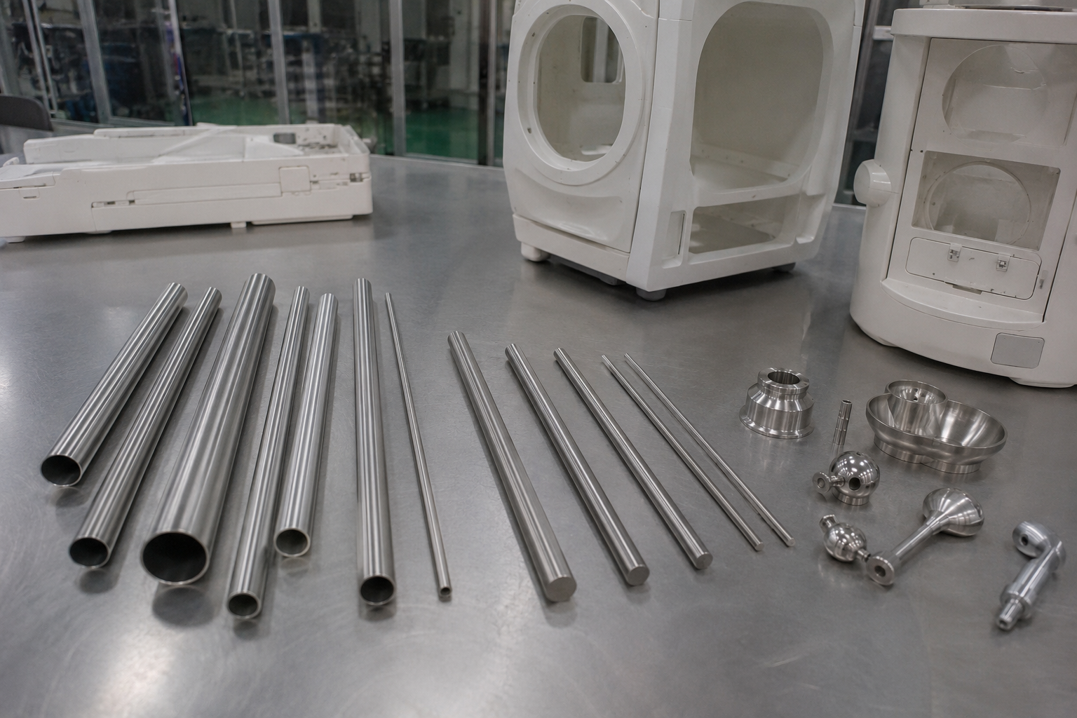
The correct objective is not to eliminate every deviation.
It is to establish and maintain a controlled range of variation within which the part and assembly continue to perform their intended functions.
What Does Tolerance Mean?
A nominal dimension is the stated reference or target size of a feature.
A tolerance defines the permitted variation associated with a specified characteristic.
For example, a drawing might control:
- The diameter of a shaft;
- the distance between two holes;
- the straightness of a tube;
- the flatness of a sealing face;
- the position of a threaded feature;
- the runout of a rotating component;
- the profile of a complex surface;
- the roughness of a patient-contact surface.
These are not interchangeable requirements.
A part can meet its diameter limits and still be:
- Bent;
- oval;
- tapered;
- misaligned;
- incorrectly positioned;
- unsuitable for assembly.
The word “tolerance” should therefore be linked to an explicitly defined characteristic.
Tolerance Is Not Zero Deviation
No manufacturing process produces every part at an exact mathematical nominal value.
Measurement also contains uncertainty.
A practical tolerance establishes the variation that can be accepted without compromising:
- Function;
- safety;
- assembly;
- interchangeability;
- durability;
- cleanliness;
- manufacturing control;
- regulatory requirements.
A specification of 10.000 mm does not mean that every acceptable part must measure exactly 10.000 mm.
It means the drawing, model, or specification should define:
- What feature is being measured;
- how size is interpreted;
- the upper and lower limits;
- the relevant reference condition;
- how conformity will be determined.
Tighter Is Not Automatically Better
An unnecessarily tight tolerance may increase:
- Manufacturing operations;
- tool wear;
- inspection time;
- scrap;
- rework;
- lead time;
- supplier dependence;
- measurement disagreement;
- cost.
It may also encourage manufacturers to use:
- Additional grinding;
- straightening;
- stress-relief cycles;
- manual correction;
- selective assembly.
These extra processes can introduce their own risks.
The design team should tighten a tolerance only where the reduced variation provides a justified functional or risk-control benefit.
Start with the Finished Device Function
Tolerance requirements should be derived from what the device and component must do.
Mating and Assembly
For mating features, define:
- Clearance;
- transition or interference;
- alignment;
- insertion force;
- extraction force;
- assembly sequence;
- allowable play;
- service disassembly.
A shaft and hole do not need independently “tight” tolerances.
They need a controlled relationship that produces the required fit.
Sealing
A seal interface may depend on:
- Diameter;
- roundness;
- flatness;
- surface texture;
- groove geometry;
- compression;
- alignment;
- material hardness.
A correct nominal diameter cannot compensate for a warped sealing face or damaged surface.
Rotating or Sliding Movement
Moving components may require control of:
- Clearance;
- coaxiality;
- runout;
- straightness;
- cylindricity;
- surface texture;
- lubrication allowance;
- thermal expansion.
Too much clearance may create vibration or unstable motion.
Too little clearance may create binding, heat, galling, or accelerated wear.
Fluid Delivery
For tubing, needles, valves, pumps, and fluid passages, relevant characteristics may include:
- Inside diameter;
- wall thickness;
- eccentricity;
- ovality;
- length;
- hole position;
- orifice geometry;
- surface condition;
- connection alignment.
Flow performance should be verified at the device level where necessary.
An inside-diameter tolerance alone may not describe an irregular or partially obstructed passage.
Load-Bearing Features
For screws, shafts, pins, brackets, and implantable components, relevant tolerances may affect:
- Section thickness;
- thread engagement;
- notch geometry;
- bearing contact;
- preload;
- fatigue stress;
- bending stiffness;
- fracture resistance.
The tolerance should be connected to structural analysis and verification.
Sensors and Diagnostic Components
Tolerance may affect:
- Sensor position;
- optical alignment;
- magnetic gap;
- probe depth;
- thermal response;
- electrical isolation;
- calibration.
These components may require tight location or profile control even where the basic material dimensions are relatively broad.
Use Risk Management to Identify Critical Characteristics
ISO 14971 risk management provides a framework for identifying hazards, evaluating risks, implementing controls, and monitoring those controls throughout the medical-device lifecycle.
A dimensional or geometric characteristic may be considered critical when variation could contribute to:
- Loss of essential function;
- leakage;
- incorrect delivery;
- loss of fixation;
- excessive wear;
- component fracture;
- jamming;
- unintended movement;
- difficult cleaning;
- incorrect assembly;
- loss of interchangeability.
Not every dimension on a drawing has the same risk significance.
A practical classification might distinguish:
| Characteristic Category | Possible Meaning | Typical Control |
|---|---|---|
| Safety-critical | Variation can contribute directly to unacceptable risk | Strong design justification, validated measurement and enhanced control |
| Function-critical | Variation can prevent intended performance or assembly | Defined capability, inspection and change control |
| Process-important | Variation affects downstream manufacturing stability | Process monitoring and supplier reporting |
| Reference | Information only and not independently toleranced | No separate acceptance unless stated |
| Cosmetic | Appearance without governing functional effect | Visual or agreed appearance standard |
The terminology should follow the manufacturer’s controlled quality system.
Separate Design Inputs from Design Outputs
A design input may state:
- The device shall deliver a defined flow;
- the joint shall withstand a specified load;
- the seal shall not leak;
- the instrument shall articulate through a stated angle;
- components shall be interchangeable.
A design output converts those needs into controlled specifications such as:
- Diameter limits;
- positional tolerance;
- flatness;
- wall thickness;
- surface texture;
- material;
- heat treatment;
- inspection method.
The tolerance is therefore a design output.
It should be verified to show that it correctly represents the design input.
The U.S. FDA Quality Management System Regulation became effective in 2026 and incorporates ISO 13485:2016 into the device quality-system framework.
This does not create a universal FDA tolerance table.
The manufacturer remains responsible for defining and controlling appropriate device specifications.
Raw-Material Tolerances and Finished-Part Tolerances Are Different
One of the most common procurement mistakes is sending a finished-part requirement to a raw-material supplier without distinguishing the delivery stage.
Raw-Material Tolerances
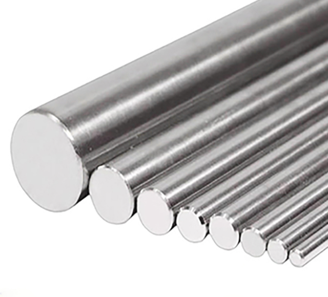
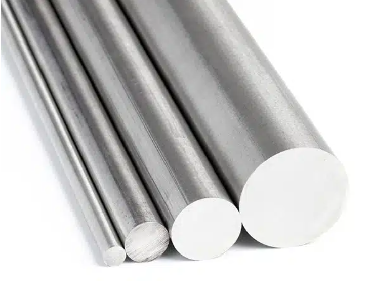
A titanium or nickel-alloy bar order may define:
- Diameter;
- ovality;
- length;
- straightness;
- surface condition;
- machining allowance;
- end condition.
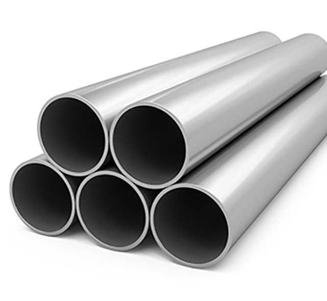
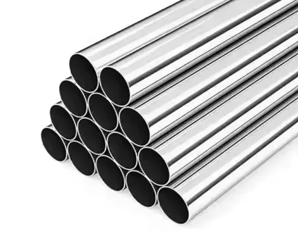
A tube order may define:
- Outside diameter;
- inside diameter;
- wall thickness;
- eccentricity;
- ovality;
- straightness;
- length;
- surface;
- end preparation.
These requirements describe the delivered stock.
Machining-Blank Tolerances
A cut blank may additionally require:
- Cut length;
- squareness;
- saw allowance;
- concentric skin removal;
- end-face condition;
- identification;
- orientation;
- machining datum.
Finished-Component Tolerances
The machined component may require:
- Precision fits;
- hole position;
- thread geometry;
- coaxiality;
- perpendicularity;
- runout;
- flatness;
- profile;
- surface texture.
The original mill normally cannot certify these final characteristics before the machining operations exist.
Product Standards Do Not Replace the Part Drawing
ASTM B348 titanium bar requirements cover titanium and titanium-alloy bars and billets.
ASTM B446 nickel alloy bar requirements cover selected nickel-chromium-molybdenum alloy rod and bar products.
These standards may define:
- Product form;
- chemistry;
- mechanical properties;
- condition;
- testing;
- dimensional requirements;
- marking.
They do not define the final medical component’s:
- Bore alignment;
- connection geometry;
- sealing face;
- thread relationship;
- assembly clearance;
- complete GD&T.
A complete purchase order should connect the raw-material standard to the customer drawing and supplementary requirements.
Straightness Deserves Separate Attention
A long bar can meet its diameter tolerance and still create unstable machining if it is not sufficiently straight.
Poor straightness may contribute to:
- Automatic bar-feeder vibration;
- spindle runout;
- variable cutting depth;
- chatter;
- uneven stock removal;
- inaccurate laser alignment;
- difficulty entering guide bushings;
- excessive scrap.
ASTM F2819-24 straightness measurement provides test methods for bar, rod, tubing, and wire used for medical devices.
The specification should define:
- Applicable product form;
- support method;
- measurement span;
- rotation method;
- indicator location;
- maximum permitted deviation;
- reporting format.
“Straight material” or “precision straightness” is not a measurable acceptance requirement.
Diameter, Roundness, Cylindricity, and Runout Are Different
Diameter
Diameter limits control a size characteristic.
They do not automatically control the entire axis or surface.
Roundness
Roundness controls each evaluated circular cross-section.
A part may have acceptable roundness at several sections but still be tapered or bent.
Cylindricity
Cylindricity controls the three-dimensional cylindrical surface.
It does not require a datum.
Runout
Runout evaluates variation when a part is rotated relative to a datum axis.
It is often relevant to:
- Rotating shafts;
- bearing surfaces;
- sealing diameters;
- tool interfaces;
- concentric assemblies.
The appropriate characteristic should be selected from the functional requirement.
Plus-or-Minus Tolerancing Is Not Enough for Every Feature
A drawing that locates a hole using two ± coordinate dimensions can create:
- A rectangular acceptance zone;
- ambiguous functional relationships;
- conflicting inspection interpretations.
Position tolerancing can provide a clearer relationship to functional datums and a defined tolerance zone.
ISO 1101 geometrical tolerancing establishes the ISO language for geometrical specifications.
ASME Y14.5 GD&T provides a widely used alternative system.
The drawing should state which system and edition apply.
The two systems should not be casually mixed because:
- Default rules may differ;
- symbols may have different context;
- material-boundary concepts may differ;
- datum interpretation may differ;
- inspection software may apply different defaults.
Establish a Functional Datum System
A datum system should reflect how the part:
- Mounts;
- seats;
- aligns;
- rotates;
- seals;
- interfaces with adjacent parts.
ISO 5459 datum systems provides terminology and rules for indicating and understanding datums.
A useful datum strategy may identify:
- Primary seating plane;
- secondary locating diameter;
- tertiary anti-rotation feature.
An arbitrary datum selected only because it is easy to measure may produce a technically precise inspection that does not represent assembly function.
Avoid Over-Datuming
Too many datum references can:
- Overconstrain the part;
- create inconsistent setups;
- conflict with actual assembly;
- make inspection difficult;
- drive unnecessary machining.
The minimum datum system that adequately represents function is usually preferable.
Datum simulators and fixture contact should also represent the intended specification.
Control Tolerance Stack-Up
A medical-device assembly may contain several parts whose variations accumulate.
Examples include:
- Implant and instrument interfaces;
- valve assemblies;
- pump mechanisms;
- robotic joints;
- optical systems;
- sensor stacks;
- housing and cover assemblies.
A tolerance stack should consider:
- Each contributing dimension;
- geometric variation;
- material condition;
- assembly sequence;
- deformation;
- temperature;
- preload;
- coating thickness;
- wear.
Worst-Case Analysis
Worst-case analysis assumes every contributing characteristic reaches its least favorable permitted condition simultaneously.
It can be appropriate where:
- Interchangeability must be guaranteed;
- failure consequences are high;
- selective assembly is not permitted;
- production volume is limited.
It may lead to unnecessarily tight individual tolerances when the assumed combination is extremely improbable.
Statistical Analysis
Statistical stack analysis considers expected distributions and process variation.
It may be useful where:
- Processes are stable;
- sufficient data exist;
- distribution assumptions are justified;
- risk controls permit statistical treatment.
Statistical analysis does not remove the need for part-level specifications.
The selected approach should be documented and linked to risk.
Consider Maximum and Least Material Conditions Carefully
Material-condition modifiers may provide useful functional tolerance where a feature’s size affects available assembly clearance.
They can support:
- Functional gauging;
- bonus tolerance;
- interchangeability;
- simplified inspection.
They should not be added only to make manufacturing easier.
The design team should confirm that the material-boundary concept correctly represents the assembly.
Define Fits by Function
ISO 286 limits and fits provides a standardized system of tolerance classes for cylindrical features and opposing parallel surfaces.
A fit may be:
- Clearance;
- transition;
- interference.
The correct fit depends on:
- Required motion;
- alignment;
- assembly force;
- disassembly;
- temperature;
- lubrication;
- material pair;
- surface treatment;
- wall thickness.
A common fit designation should not be copied into a medical device without checking the actual materials and application.
Temperature Affects Dimensional Verification
Nickel alloys, titanium alloys, stainless steels, polymers, ceramics, and measuring systems expand at different rates.
Dimensional results may be influenced by:
- Part temperature;
- gauge temperature;
- room temperature;
- handling;
- machining heat;
- cleaning or sterilization;
- stabilization time.
For tight tolerances, the inspection plan should define:
- Reference temperature;
- environmental range;
- stabilization period;
- thermal compensation;
- material coefficient used;
- recording requirements.
A part measured immediately after machining may not produce the same result after thermal stabilization.
Titanium Alloy Processing and Dimensional Stability
Titanium alloys can present manufacturing challenges related to:
- Low elastic modulus;
- workpiece deflection;
- springback;
- cutting heat;
- residual stress;
- tool wear;
- thin-wall distortion.
A dimension may appear correct while clamped and change after release.
The machining plan may need:
- Rigid fixturing;
- balanced material removal;
- staged machining;
- stress-management procedures;
- sharp tooling;
- controlled coolant delivery;
- intermediate inspection;
- final stabilization.
The alloy grade alone does not determine the achievable tolerance.
Nickel Alloy Processing and Dimensional Stability
Many nickel alloys can present challenges related to:
- High cutting forces;
- work hardening;
- heat generation;
- tool wear;
- residual stress;
- burr formation;
- thin-wall distortion.
The process may require:
- Rigid setup;
- controlled depth of cut;
- suitable cutting tools;
- stable tool-life limits;
- balanced stock removal;
- in-process inspection;
- defined final finishing.
A supplier’s ability to produce one successful sample does not demonstrate stable production capability.
Nitinol Requires a Separate Functional Approach
Nickel-titanium shape-memory alloy can exhibit:
- Superelasticity;
- shape memory;
- recoverable strain;
- temperature-dependent geometry.
Its dimensions may be influenced by:
- Phase condition;
- test temperature;
- cold work;
- heat treatment;
- shape setting;
- restraint;
- loading history.
A Nitinol drawing may need to distinguish:
- Free-state geometry;
- constrained geometry;
- delivery temperature;
- test temperature;
- transformation condition;
- shape-recovery requirement.
Conventional rigid-part inspection logic may not be sufficient.
Thin-Wall Parts Can Distort During Measurement
Thin tubes, clips, shells, and small rings can deform under:
- Micrometer force;
- CMM probe force;
- fixture clamping;
- air-gauge pressure;
- handling.
The measurement method should not significantly alter the measurand.
The inspection plan may need to define:
- Contact force;
- support;
- orientation;
- number of measurement points;
- non-contact method;
- free-state or restrained-state measurement.
A more precise instrument can still produce a misleading result if it deforms the part.
Surface Texture Is Not a Dimensional Tolerance
ISO 21920-1 surface texture establishes rules for indicating profile-based surface texture in technical product documentation.
A complete surface requirement may need to identify:
- Parameter;
- limit;
- filter;
- evaluation length;
- direction;
- manufacturing lay;
- measurement location;
- number of traces;
- treatment condition.
“Ra 0.4” alone may be incomplete where the drawing does not define the applicable standard and conditions.
Surface texture also does not fully describe:
- Scratches;
- pits;
- burrs;
- cracks;
- embedded particles;
- discoloration;
- edge condition;
- cleanliness.
These may require separate acceptance criteria.
Different Surfaces Need Different Requirements
Sealing Surfaces
May require control of:
- Flatness;
- waviness;
- roughness;
- scratches;
- coating;
- cleanliness.
Sliding Surfaces
May require control of:
- Roughness;
- lay;
- clearance;
- hardness;
- lubrication;
- wear.
Patient-Contact Surfaces
May require control of:
- Final finish;
- residues;
- particles;
- surface treatment;
- biological evaluation.
Bone-Contacting Surfaces
May intentionally use a controlled texture or coating.
The requirement should follow the validated device design.
Adhesive-Bonding Surfaces
May require a defined surface preparation rather than minimum roughness alone.
Surface Finishing Can Change Dimensions
Operations that may alter dimensions include:
- Grinding;
- polishing;
- electropolishing;
- passivation-related cleaning;
- blasting;
- acid etching;
- anodizing;
- coating;
- plating;
- laser processing.
The drawing should state whether dimensions apply:
- Before finishing;
- after finishing;
- after coating;
- after cleaning;
- in the final device condition.
A component machined exactly to final size before electropolishing may become undersized after controlled material removal.
Heat Treatment Can Change Geometry
Heat treatment may cause:
- Distortion;
- stress relaxation;
- scale;
- dimensional growth or shrinkage;
- phase-related changes;
- hardness changes.
The process plan should establish:
- Whether heat treatment occurs before or after final machining;
- whether straightening is permitted;
- when final inspection occurs;
- whether reinspection is required after thermal exposure.
An inspection report created before the final heat treatment may not represent the delivered condition.
Welding and Joining Affect Tolerance
Welding, brazing, soldering, adhesive bonding, and mechanical fastening may affect:
- Alignment;
- flatness;
- angularity;
- shrinkage;
- gap;
- residual stress;
- local distortion.
An assembly drawing should define:
- Pre-assembly dimensions;
- final assembly dimensions;
- fixture datums;
- welding sequence;
- post-weld inspection;
- acceptable distortion.
Part tolerances should not be so tight that normal joining distortion makes the assembly impractical without a functional reason.
Sterilization and Reprocessing Can Affect Dimensions
Repeated processing may influence an assembly through:
- Thermal expansion;
- residual-stress relaxation;
- coating changes;
- seal compression;
- polymer creep;
- joint wear;
- corrosion products;
- deposits.
Most metallic bulk dimensions may remain stable under appropriate conditions, but the complete device should be evaluated under the intended processing cycle where dimensional or functional change is credible.
The raw-material supplier cannot establish the reusable life of the final device.
Select the Measurement Method from the Characteristic
Calipers
May be useful for:
- General outside dimensions;
- length;
- accessible steps.
They may not be suitable for very tight tolerances or complex geometry.
Micrometers
May be useful for:
- Outside diameter;
- thickness;
- controlled two-point measurements.
Contact force and part deformation should be considered.
Bore Gauges and Air Gauges
May be useful for:
- Inside diameter;
- bore variation;
- production comparison.
Mastering, taper, surface and cleanliness can affect results.
Coordinate Measuring Machines
May be useful for:
- Position;
- profile;
- complex datum relationships;
- three-dimensional geometry.
CMM results depend on:
- Machine capability;
- probing system;
- fixture;
- point strategy;
- alignment;
- software;
- filtering;
- operator;
- uncertainty.
ISO 10360 CMM verification provides acceptance and reverification requirements for specified CMM applications.
Optical Systems
May be useful for:
- Small features;
- edge geometry;
- non-contact measurement;
- flexible parts.
Results can depend on:
- Focus;
- lighting;
- edge-detection algorithm;
- surface reflectivity;
- magnification;
- calibration.
Surface Profilometers
May be used for defined profile surface-texture parameters.
The stylus, filter and evaluation conditions must match the specification.
Computed Tomography
May support inspection of:
- Internal channels;
- inaccessible geometry;
- complex additive parts.
Resolution, thresholding, artefacts and task-specific uncertainty require control.
No single measurement technology is best for every characteristic.
Resolution Is Not Measurement Accuracy
A display that shows 0.001 mm increments does not prove that the system measures with 0.001 mm uncertainty.
Measurement performance can be affected by:
- Calibration;
- repeatability;
- reproducibility;
- linearity;
- bias;
- temperature;
- fixturing;
- operator;
- method;
- software;
- part geometry.
Instrument resolution should not be used as the sole basis for selecting inspection equipment.
Calibration Is Necessary but Not Sufficient
A calibration certificate can help establish metrological traceability and instrument performance.
It does not prove that:
- The correct measurement method was used;
- the fixture was appropriate;
- the operator selected the correct datum;
- the software strategy matched the drawing;
- the part was thermally stable;
- the measurement uncertainty was suitable.
The inspection process itself should be controlled.
Measurement Uncertainty Affects Acceptance
ISO 14253-1 conformity decisions provides decision rules for evaluating conformity or nonconformity while considering measurement uncertainty.
When a measured value is close to a specification limit, the parties should understand:
- Applicable decision rule;
- measurement uncertainty;
- guard band where used;
- customer and supplier responsibilities;
- treatment of indeterminate results.
Without an agreed decision rule, a customer and supplier may measure the same part and reach different conclusions.
Define Acceptance Rules Before Production
The purchase agreement should establish:
- Governing drawing;
- tolerancing standard;
- measurement method;
- reference temperature;
- sampling;
- uncertainty treatment;
- rounding rule;
- retest procedure;
- dispute-resolution method.
These requirements should not be invented after a dimensional disagreement occurs.
Process Capability Is Not the Same as Part Conformity
A process-capability study evaluates how process variation compares with specification limits under defined assumptions.
It may help assess:
- Centering;
- variation;
- stability;
- expected nonconformance;
- improvement priorities.
It does not prove that every individual part conforms.
Capability indices are meaningful only when:
- The process is stable;
- measurement error is understood;
- distribution assumptions are appropriate;
- data represent the production process;
- specification limits are valid.
A high Cpk value cannot compensate for an incorrect drawing or unsuitable measurement method.
100% Inspection Does Not Guarantee Zero Defects
Inspecting every part may be justified for selected critical characteristics.
However, 100% inspection can still be affected by:
- Measurement error;
- operator fatigue;
- incorrect programs;
- fixture wear;
- false acceptance;
- false rejection;
- data-transfer errors.
Process control and prevention remain important.
The inspection level should be based on:
- Risk;
- process capability;
- supplier history;
- characteristic type;
- measurement feasibility;
- regulatory and customer requirements.
Sampling Must Be Defined
A sampling requirement should identify:
- Lot definition;
- sample size;
- randomization;
- acceptance criteria;
- escalation;
- reduced or tightened inspection;
- handling of nonconformance.
“Random inspection” is not a complete sampling plan.
For safety-critical dimensions, sampling may be combined with process controls, validated tooling, automated monitoring or 100% verification where justified.
Control Digital Models and Drawing Revisions
Medical-device manufacturing increasingly uses model-based definitions.
The supplier should know:
- Whether the 3D model or 2D drawing governs;
- which revision applies;
- which dimensions are basic;
- which annotations are authoritative;
- how embedded product-manufacturing information is interpreted;
- whether derived dimensions are allowed.
A supplier should not manufacture from an uncontrolled screenshot or outdated PDF.
Use a Ballooned Drawing for Inspection Planning
A ballooned drawing can link every controlled characteristic to:
- Inspection item number;
- measurement method;
- sampling frequency;
- actual result;
- acceptance status;
- instrument.
It can help identify:
- Missing dimensions;
- duplicate controls;
- unmeasurable requirements;
- conflicting notes;
- unclear datums.
The ballooned drawing should remain linked to the approved revision.
First-Article Inspection Is Not Process Validation
A first-article inspection can demonstrate that one initial production result meets specified characteristics.
It does not prove that future production will remain stable.
Ongoing control may require:
- Process validation;
- control plan;
- capability studies;
- tool-life controls;
- in-process inspection;
- preventive maintenance;
- change control.
A perfect first article produced through extensive manual adjustment may not represent normal production.
Control Critical Characteristics Through the Process
A control plan may identify:
| Process Stage | Possible Characteristic | Possible Control |
|---|---|---|
| Incoming bar | Diameter, straightness, heat identity | Incoming inspection and certificate review |
| Cutting | Blank length, squareness | Saw setup and sampling |
| Rough machining | Stock distribution, datum preparation | In-process measurement |
| Heat treatment | Distortion, condition | Controlled cycle and post-process inspection |
| Finish machining | Size, position, runout, profile | Validated machining and final measurement |
| Polishing | Material removal, roughness | Process limits and surface inspection |
| Coating | Thickness, final dimensions | Coating control and post-coating verification |
| Cleaning | Residues and handling damage | Validated cleaning and visual inspection |
| Assembly | Fit, preload, movement, leakage | Functional testing |
| Final inspection | Drawing and device requirements | Approved acceptance plan |
What Should an Inspection Report Contain?
A useful dimensional report may identify:
- Part number;
- drawing revision;
- lot or serial number;
- material heat;
- characteristic number;
- nominal value;
- upper and lower limits;
- actual measured value;
- units;
- measurement method;
- instrument identification;
- inspection date;
- inspector;
- acceptance result;
- deviation reference.
For GD&T characteristics, the report may also need:
- Datum setup;
- alignment;
- software routine;
- point strategy;
- fixture;
- filtering;
- uncertainty where relevant.
A report containing only “PASS” provides less information than actual measurement results.
Understand the Role of the MTR
An MTR may provide:
- Alloy grade;
- UNS designation;
- heat number;
- chemistry;
- mechanical properties;
- heat-treatment condition;
- product standard;
- selected tests.
It does not normally prove:
- Finished-part dimensions;
- GD&T;
- assembly fit;
- surface cleanliness;
- device performance;
- measurement-system capability.
The MTR and dimensional inspection report serve different purposes.
Understand the Role of the Certificate of Conformance
A Certificate of Conformance is the supplier’s declaration that the delivered product meets the stated order requirements.
It may be valuable within the quality system.
It does not automatically contain:
- Actual dimensions;
- measurement uncertainty;
- inspection method;
- raw test data.
Where actual values are required, the purchase order should request a dimensional inspection report rather than only a CoC.
Supplier Quality-System Certificates Have Limits
ISO 13485 quality management provides medical-device-sector quality-management requirements.
A supplier certificate should be checked for:
- Legal company name;
- site;
- scope;
- manufacturing or distribution activity;
- validity;
- certification body.
ISO 13485 certification does not prove that a particular part meets its drawing.
ISO 9001 or ISO 13485 should be evaluated together with:
- Process capability;
- actual inspection evidence;
- calibration;
- traceability;
- nonconformance control;
- change control.
Laboratory and Calibration Scope Must Be Relevant
ISO/IEC 17025 laboratory competence supports confidence in testing and calibration laboratories.
The buyer should verify whether the required activity is included in the relevant scope, such as:
- Dimensional calibration;
- surface measurement;
- chemical analysis;
- mechanical testing;
- CMM calibration;
- gauge calibration.
A laboratory accredited for chemical testing is not automatically accredited for dimensional calibration.
Supplier Change Control Is Critical
Changes that may affect dimensional capability include:
- Original mill;
- bar diameter;
- material condition;
- heat treatment;
- machine tool;
- fixture;
- cutting tool;
- CNC program;
- coolant;
- subcontractor;
- polishing process;
- measurement method;
- CMM software;
- inspection location.
The agreement should define which changes require:
- Notification;
- customer approval;
- new first article;
- revalidation;
- capability study.
A part may still meet one inspected dimension while an uncontrolled change affects long-term process consistency.
Raw-Material Supplier and Component Manufacturer Responsibilities
Device Manufacturer
Typically controls:
- Intended use;
- risk management;
- design inputs;
- design outputs;
- GD&T;
- critical characteristics;
- validation;
- final regulatory responsibility.
Component Manufacturer
Typically controls:
- Manufacturing process;
- fixtures;
- machining;
- in-process inspection;
- final dimensions;
- process capability;
- nonconformance;
- change control.
Raw-Material Supplier
Typically controls:
- Alloy;
- product form;
- material condition;
- raw dimensions;
- straightness;
- surface;
- material tests;
- heat traceability;
- delivery documentation.
A raw-material supplier can support manufacturability discussions.
It should not independently approve final medical-device tolerances.
How a Material Supplier Can Support Buyers
A qualified alloy-material supplier may help buyers:
- Compare available bar or tube conditions;
- confirm standard dimensional tolerances;
- review achievable diameter and straightness ranges;
- identify machining allowance;
- clarify actual versus specification-limit data;
- arrange additional dimensional inspection when ordered;
- preserve heat traceability after cutting;
- flag requirements that are missing or conflicting;
- coordinate third-party testing.
The supplier’s contribution should remain within its demonstrated capabilities and approved responsibility.
Component-Specific Tolerance Questions
| Component | Key Questions |
|---|---|
| Precision shaft | What controls rotation: diameter, straightness, runout or cylindricity? |
| Thin-wall tube | Are OD, ID, wall, eccentricity and ovality all relevant? |
| Pump component | Which clearances control flow, leakage and wear? |
| Implant screw | Which dimensions control engagement, torque and fatigue? |
| Robotic joint | Which datums reproduce the actual assembly? |
| Sensor sheath | Does wall variation affect strength or response time? |
| Guidewire stock | What straightness and free-state condition are needed? |
| Seal housing | Are flatness and surface texture more important than nominal diameter? |
| Instrument jaw | Which position and profile requirements control alignment? |
| Coated component | Do dimensions apply before or after coating? |
Practical Tolerance-Development Workflow
Step 1: Define Intended Use
Identify:
- Device;
- component;
- patient or user interaction;
- environment;
- expected life;
- assembly.
Step 2: Define Function
Identify requirements for:
- Fit;
- motion;
- sealing;
- flow;
- load;
- alignment;
- interchangeability;
- cleaning.
Step 3: Identify Risks
Use the risk-management process to determine which variations could create unacceptable outcomes.
Step 4: Select the Tolerancing System
State:
- ISO GPS or ASME Y14.5;
- edition;
- units;
- drawing hierarchy;
- model or drawing authority.
Step 5: Establish Datums
Base the datum system on functional mounting and assembly.
Step 6: Perform Tolerance Analysis
Evaluate:
- Individual features;
- assembly stack;
- deformation;
- temperature;
- finishing;
- wear.
Step 7: Review Manufacturability
Confirm:
- Material;
- product form;
- process;
- achievable capability;
- inspection method;
- cost.
Step 8: Define Measurement
State:
- Instrument;
- method;
- setup;
- reference condition;
- uncertainty;
- sampling;
- decision rule.
Step 9: Validate Function
Use:
- Assembly testing;
- leakage testing;
- load testing;
- motion testing;
- flow testing;
- simulated use;
- lifecycle testing.
Step 10: Maintain Control
Monitor:
- Process capability;
- tool wear;
- measurement systems;
- supplier changes;
- nonconformances;
- production feedback.
Common Mistakes in Medical Alloy Tolerance Control
1. Specifying the Tightest Possible Tolerance
Use the tolerance required by function and risk.
2. Using ± Dimensions for Every Feature
Use geometrical controls where form, position, orientation or runout governs function.
3. Selecting Arbitrary Datums
Datums should reproduce assembly and function.
4. Confusing Diameter with Roundness
A size limit does not fully control form.
5. Confusing Straightness with Runout
They evaluate different relationships.
6. Treating Surface Roughness as a Size Tolerance
Specify surface texture separately.
7. Applying the Same Roughness to Every Surface
Different functional zones require different surfaces.
8. Using General Drawing Tolerances for Critical Features
Critical characteristics should be individually specified.
9. Sending Finished-Part Tolerances to a Raw-Material Mill
Separate stock and final-component requirements.
10. Ignoring Straightness of Machining Stock
Diameter alone may not support stable feeding or machining.
11. Ignoring Thermal Conditions
Part and gauge temperature can affect tight measurements.
12. Measuring Flexible Parts Without Defining Restraint
The measuring force or fixture may change the result.
13. Assuming CMM Means Accurate
The machine, method, program and uncertainty must fit the characteristic.
14. Using Instrument Resolution as Accuracy
Display digits do not define uncertainty.
15. Ignoring Measurement Uncertainty at the Limit
Use an agreed conformity decision rule.
16. Treating Calibration as Complete Measurement Validation
The full measurement process must be appropriate.
17. Treating a First Article as Proof of Stable Production
Evaluate ongoing process control.
18. Treating Cpk as Product Acceptance
Capability and conformity are different questions.
19. Demanding 100% Inspection Without a Risk Rationale
Inspection should complement process prevention.
20. Inspecting Before the Final Dimension-Changing Process
Final verification should represent the delivery condition.
21. Ignoring Polishing or Coating Removal
Finishing can change dimensions.
22. Ignoring Heat-Treatment Distortion
Inspection before heat treatment may not represent the final part.
23. Accepting a “PASS” Report Without Actual Data
Request actual values where needed.
24. Treating the MTR as a Dimensional Report
MTRs and dimensional reports have different purposes.
25. Treating ISO 13485 as Proof of Part Conformity
It is a quality-system standard.
26. Allowing Unapproved Measurement-Method Changes
A different method can produce a different result.
27. Allowing Supplier Process Changes Without Review
Changes may affect dimensional stability.
28. Expecting the Material Supplier to Approve Final Tolerances
Final design approval remains with the device manufacturer.
RFQ Checklist for Medical Alloy Parts and Raw Materials
Before requesting a quotation, define:
- Device type;
- component name;
- intended function;
- patient-contact status;
- load;
- motion;
- seal requirement;
- fluid requirement;
- expected service life;
- sterilization or cleaning exposure;
- governing drawing;
- drawing revision;
- model revision;
- drawing or model precedence;
- tolerancing system;
- tolerancing-standard edition;
- units;
- alloy;
- UNS designation;
- product standard;
- product form;
- delivery condition;
- heat treatment;
- raw diameter or OD;
- ID;
- wall thickness;
- ovality;
- eccentricity;
- raw straightness;
- raw length;
- machining allowance;
- surface condition;
- finished dimensions;
- fits;
- flatness;
- straightness;
- roundness;
- cylindricity;
- perpendicularity;
- parallelism;
- angularity;
- position;
- profile;
- runout;
- datum system;
- material-condition modifiers;
- surface-texture parameter;
- surface-texture limit;
- surface-texture direction;
- burr and edge requirements;
- coating thickness;
- pre- or post-coating dimensions;
- pre- or post-polishing dimensions;
- measurement reference temperature;
- inspection method;
- fixture or restraint condition;
- measurement uncertainty requirement;
- conformity decision rule;
- sampling plan;
- critical-characteristic classification;
- first-article requirement;
- capability-study requirement;
- actual dimensional report;
- ballooned drawing;
- instrument identification;
- calibration requirement;
- ISO/IEC 17025 requirement;
- MTR;
- Certificate of Conformance;
- heat-to-piece traceability;
- marking;
- packaging;
- nonconformance notification;
- deviation approval;
- source-change notification;
- process-change notification;
- measurement-method change notification;
- record-retention period.
Frequently Asked Questions
What is the difference between nominal size and tolerance?
The nominal size is the stated reference size. The tolerance defines the permitted variation for a specified characteristic.
Does a tighter tolerance always improve medical-device safety?
No. It improves control only when the reduced variation addresses a real functional or risk requirement. Unnecessary tightening can increase cost and manufacturing complexity.
Is diameter tolerance enough for a precision shaft?
Not necessarily. Straightness, roundness, cylindricity, runout and surface texture may also affect function.
What is the difference between dimensional tolerance and GD&T?
Dimensional tolerance controls quantities such as size or distance. GD&T controls geometric characteristics such as form, orientation, location, profile and runout.
Can ISO and ASME GD&T be used on the same drawing?
They should not be mixed without explicitly defining the governing rules and interpretation. Their default conventions are not identical.
Does ASTM B348 define the final tolerance of a titanium medical component?
No. It defines requirements for titanium bars and billets. The final component drawing controls finished-part geometry.
Why is raw-bar straightness important?
It can affect automatic feeding, spindle stability, laser alignment, cutting consistency and downstream dimensional capability.
Is surface roughness part of dimensional tolerance?
No. Surface texture is specified and verified separately, although manufacturing processes can influence both.
Does a calibrated CMM guarantee an accurate inspection result?
No. Accuracy also depends on the program, fixture, probe, alignment, sampling strategy, environment and task-specific uncertainty.
What happens when a measured result is close to the tolerance limit?
The applicable decision rule and measurement uncertainty should be considered. ISO 14253-1 provides one recognized framework.
Does 100% inspection guarantee zero defective parts?
No. Inspection itself can contain errors. Stable manufacturing processes and suitable measurement systems remain necessary.
Does an MTR prove the dimensions of the final component?
No. An MTR generally reports material and heat-level information. Finished dimensions require a dimensional inspection report.
Does ISO 13485 specify medical-part tolerances?
No. It defines quality-management-system requirements. Device manufacturers establish tolerances through design and risk-management processes.
Can the raw-material supplier decide the final part tolerance?
The supplier can provide capability and manufacturability information. Final tolerance approval belongs to the device manufacturer’s controlled design process.
Conclusion
Tolerance control for medical equipment alloy parts is not a race toward zero deviation.
It is a structured engineering process that connects:
- Intended use;
- device function;
- risk management;
- design inputs;
- design outputs;
- material and product form;
- raw-stock tolerances;
- machining allowance;
- GD&T;
- datum systems;
- surface texture;
- assembly stack-up;
- thermal effects;
- manufacturing capability;
- measurement uncertainty;
- acceptance rules;
- inspection;
- traceability;
- supplier change control;
- final-device verification.
Raw-material standards, engineering drawings, MTRs, dimensional inspection reports, quality-system certificates, calibration records, and device-validation reports provide different forms of evidence.
None of them should be used as a substitute for all the others.
The goal is not to request the smallest numerical tolerance available.
The goal is to define the amount and type of variation that the finished medical device can safely and reliably accommodate—and then establish a manufacturing and measurement system capable of controlling that variation consistently.