
Which Tube Properties Matter Most for Heat Exchanger Tube Expansion?
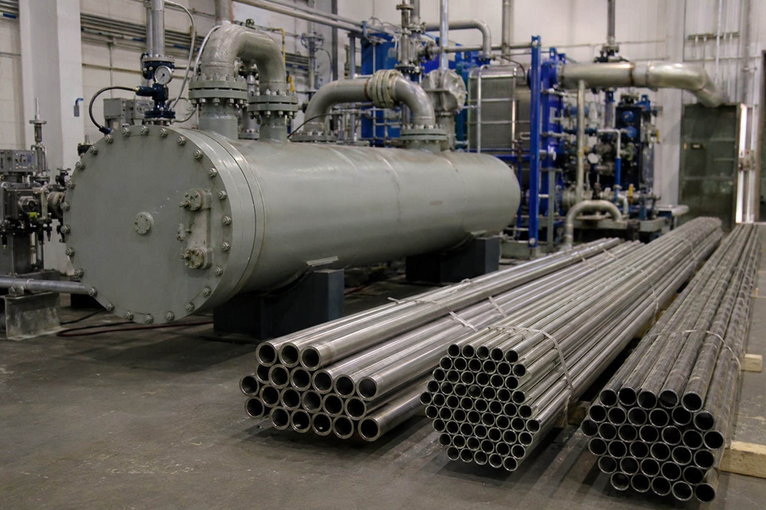
Tube expansion is one of the most important assembly operations in shell-and-tube heat exchanger manufacturing. The process is used to establish controlled contact between the tube outside surface and the tubesheet hole, helping the joint provide the required tightness, axial retention, structural support, or positioning for a welded connection.
However, a reliable expanded joint is not created by tube strength alone.
A tube may fully comply with its ASTM or ASME material specification and still produce an unsatisfactory tube-to-tubesheet joint if the actual outside diameter, wall thickness, material condition, tubesheet-hole size, initial clearance, surface condition, expansion method, tooling, or process setting differs from the combination used during qualification.
The tube properties that matter most are yield behavior, tensile strength, elongation, ductility, strain-hardening response, hardness condition, dimensional accuracy, wall-thickness consistency, ovality, surface condition, heat-treatment condition, microstructural consistency, and lot-to-lot uniformity. These properties must be evaluated together with the tubesheet material, tube-hole geometry, initial clearance, expansion method, tooling, fabrication sequence, and joint acceptance criteria.
The first question should therefore not be:
“Is this tube soft enough to expand?”
A more technically useful question is:
“Can this specific tube, tubesheet, tube-hole geometry, tooling system, and expansion procedure produce a repeatable joint without cracking, excessive wall reduction, insufficient contact, unacceptable residual stress, or damage to the surrounding tubesheet?”
This article explains which tube properties matter, how they interact with joint design and manufacturing variables, what buyers should include in an RFQ, and how fabricators can reduce expansion variability before full production begins.
Tube Expansion Is a Joint-System Problem
A tube-to-tubesheet joint contains several interacting material, dimensional, geometric, and process variables.
The tube is important, but it is only one part of the system.
| Variable Group | Typical Variables | Possible Effect on the Joint |
|---|---|---|
| Tube material | Alloy, condition, yield strength, tensile strength, ductility and hardness | Plastic deformation, work hardening, recovery and fracture resistance |
| Tube dimensions | OD, wall thickness, ID, ovality, straightness and tube-end condition | Initial clearance, tool fit, required expansion and local wall reduction |
| Tubesheet material | Alloy, strength, hardness, thickness, cladding and heat treatment | Hole deformation, elastic recovery and residual contact pressure |
| Tube-hole geometry | Diameter, tolerance, roughness, grooves, chamfers and hole roundness | Initial contact, friction, mechanical locking and transition-zone geometry |
| Expansion method | Roller, hydraulic, flexible-element, hybrid or another approved method | Loading distribution, friction, local strain and residual stress |
| Expansion setting | Torque, hydraulic pressure, mandrel travel, wall reduction or diameter increase | Final contact, thinning, deformation and joint consistency |
| Expansion length | Position and length of the expanded zone | Load transfer, tube projection and transition-zone stress |
| Fabrication sequence | Expansion order, welding order, adjacent-hole sequence and re-expansion | Residual stress redistribution and local distortion |
| Surface and cleanliness | Scale, scratches, oil, debris, lubricant and machining residue | Friction, tool behavior, contamination and repeatability |
| Inspection and qualification | Leak testing, pull-out testing, sectioning, dimensional checks and NDE | Verification that the procedure produces the intended joint |
Research on tube-to-tubesheet connections commonly evaluates joint behavior through residual contact pressure, pull-out resistance, push-out resistance, leakage performance, deformation, or residual stress.
The combined effects of tube projection, initial tube-to-tubesheet clearance, and tube strain hardening demonstrate why expansion cannot be evaluated from the tube material certificate alone.
How Does a Tube-to-Tubesheet Expanded Joint Form?
Although the detailed mechanics vary with the expansion method, the process can generally be divided into three stages.
Stage 1: Initial Clearance Is Taken Up
Before expansion, the tube outside diameter is normally smaller than the tubesheet-hole diameter.
The diametral clearance can be expressed as:
Diametral clearance = Actual tubesheet-hole diameter − Actual tube OD
The radial clearance is one-half of the diametral clearance.
At the beginning of expansion, the tube diameter increases until the tube outside surface begins to contact the tubesheet bore.
If the initial clearance is larger than expected, the tube must undergo more deformation before contact begins. This can affect the amount of work hardening, wall reduction, expansion pressure, torque response, and transition-zone strain.
Stage 2: The Tube and Tubesheet Are Loaded Together
After contact begins, additional expansion loads both the tube and the surrounding tubesheet material.
The tube commonly experiences controlled plastic deformation. The tubesheet may respond elastically and, depending on the material combination, geometry, and expansion level, may also experience localized plastic deformation.
The relative behavior of the tube and tubesheet is therefore important.
A tube cannot be described as “easy to expand” without considering:
- Tubesheet strength
- Tubesheet thickness
- Hole spacing
- Ligament width
- Hole geometry
- Groove design
- Initial clearance
- Expansion method
- Expansion length
Stage 3: The Expansion Load Is Removed
When roller loading is released or hydraulic pressure is removed, the tube and tubesheet recover elastically to different degrees.
This differential unloading contributes to residual contact between the tube outside surface and the tubesheet bore.
The resulting residual contact pressure may contribute to:
- Mechanical retention
- Resistance to tube pull-out
- Joint tightness
- Tube positioning
- Support for a welded connection
The unloading process can also involve reverse yielding in parts of the tube or tubesheet. Research on reverse yielding and residual contact pressure shows why final contact conditions cannot be predicted from hardness or yield strength alone.
Tightness, Retention, and Structural Strength Are Not the Same Requirement
A tube-to-tubesheet joint may be expected to perform several functions.
These functions are related, but they are not identical.
| Joint Requirement | Engineering Meaning | Possible Verification Method |
|---|---|---|
| Tightness | Limits leakage between the shell side and tube side | Leak test, pressure test, helium test or service-specific examination |
| Axial retention | Resists tube movement or pull-out loading | Pull-out or push-out testing |
| Structural strength | Transfers specified loads through the joint | Calculation, qualification testing or code-based assessment |
| Weld support | Holds the tube in position for seal or strength welding | Dimensional and fabrication verification |
| Fatigue resistance | Withstands pressure, thermal or vibration cycles | Design assessment, testing or service qualification |
| Corrosion performance | Limits harmful crevices, contamination or local surface damage | Material selection, surface control and service-specific testing |
| Repairability | Allows defective joints or tubes to be repaired or replaced | Procedure planning and access review |
A joint with high pull-out resistance is not automatically proven leak-tight under every service condition.
Likewise, a joint that passes an initial leak test may still require review for:
- Thermal cycling
- Pressure cycling
- Tube vibration
- Axial loading
- Corrosion
- Stress relaxation
- Creep at elevated temperature
- Weld interaction
- Long-term residual contact changes
Acceptance criteria should therefore reflect the actual function of the joint.
1. Why Yield Strength Matters During Tube Expansion
Yield strength indicates the stress level at which permanent deformation begins under the applicable test conditions.
Tube expansion requires controlled permanent deformation, so yield strength affects the load, pressure, or tool movement required to enlarge the tube.
A tube with a higher yield strength will generally require more loading to initiate plastic deformation than a geometrically similar tube with a lower yield strength.
However, lower yield strength is not automatically better.
If the expansion procedure does not match the actual tube condition, possible problems include:
- Excessive wall reduction
- Local thinning
- Tube-end distortion
- Instability in thin-wall tubing
- Excessive deformation into grooves
- High transition-zone strain
- Inconsistent final contact
- Damage during re-expansion
- Difficulty maintaining uniform settings across a large tubesheet
The tubesheet yield strength must also be considered.
Residual contact depends on the combined loading and unloading behavior of the tube and tubesheet, not only the tube.
Questions buyers and fabricators should ask
| Item | Question |
|---|---|
| Minimum yield strength | Does the material meet the applicable standard? |
| Actual yield strength | How far is the lot result above the specified minimum? |
| Maximum yield strength | Is an upper limit needed for an already-qualified procedure? |
| Supplied condition | Is the tube annealed, solution annealed, cold worked, aged or supplied in another condition? |
| Lot consistency | Are the mechanical results reasonably consistent across the supplied quantity? |
| Tubesheet relationship | Has the relative strength of the tube and tubesheet been considered? |
| Qualification material | Was the mock-up produced from representative production tubing? |
A material standard often specifies minimum properties.
Two production lots can both comply with the same standard while having different actual yield-strength levels.
Where expansion response is sensitive, the purchaser, supplier, and fabricator may need to agree on additional property limits or lot-specific qualification.
2. Why Tensile Strength Must Be Evaluated With Yield Strength
Tensile strength is the maximum engineering stress reached during a tensile test.
It provides useful information about the material's strength and fracture margin, but it should not be interpreted alone.
A common oversimplification is:
Higher tensile strength = greater brittleness
That conclusion is not technically reliable.
A material can have relatively high tensile strength and still retain useful ductility. Conversely, a lower-strength material may still show poor expansion performance because of:
- Limited elongation
- Prior cold work
- Surface defects
- Weld defects
- Incorrect heat treatment
- Thin local wall
- Unfavorable microstructure
- Excessive initial clearance
- Unsuitable tooling
- Over-expansion
The relationship between yield strength and tensile strength can also provide useful context.
A material with a high yield-to-tensile ratio may have less uniform plastic deformation available between yielding and maximum tensile load than a material with a lower ratio, although the practical effect depends on the alloy, condition, geometry, and stress state.
Mechanical-property interpretation
| Property | What It Helps Indicate | What It Does Not Prove by Itself |
|---|---|---|
| Yield strength | Onset of permanent deformation | Final joint tightness |
| Tensile strength | Maximum engineering tensile stress | Brittleness or expandability |
| Yield-to-tensile ratio | Relative margin between yielding and tensile maximum | Safe expansion setting |
| Elongation | Tensile deformation before fracture in the specified test | Allowable tube expansion percentage |
| Reduction of area | Localized ductility at fracture | Complete circumferential forming behavior |
| Hardness | Local resistance to indentation and material condition | Required expansion torque or pressure |
| Elastic modulus | Elastic stiffness | Complete unloading and springback behavior |
3. Why Ductility Is Important
Ductility describes the ability of a material to undergo plastic deformation before fracture.
Adequate ductility helps a tube enlarge and conform to the tubesheet-hole geometry without cracking.
It is particularly important for:
- Thin-wall tubing
- Large initial clearance
- Grooved tubesheet holes
- Tubes with prior cold work
- Welded tubing
- Small-diameter tubing
- Joints expanded after welding
- Joints that may require controlled re-expansion
- Materials with limited forming margins
However, ductility cannot be reduced to one elongation value.
Tensile elongation is measured under a standardized uniaxial test, while tube expansion produces a different multiaxial stress and strain condition.
A minimum elongation value should therefore not be converted directly into a universal allowable expansion percentage.
Factors that may reduce usable ductility
- Excessive cold working
- Incorrect heat treatment
- Nonuniform heat treatment
- Surface cracks
- Deep scratches
- Laps or seams
- Weld discontinuities
- Excessive weld reinforcement
- Nonuniform grain structure
- Local wall-thickness reduction
- Contamination or embrittling exposure
- Repeated expansion
- Sharp groove edges
- Abrupt transition geometry
Representative mock-up testing is often more informative than relying on tensile elongation alone.
4. Why Strain Hardening Changes Expansion Behavior
Many metallic materials increase in strength as plastic deformation develops.
This behavior is commonly called strain hardening or work hardening.
During expansion, the tube does not maintain the same resistance to deformation throughout the entire process.
As plastic strain increases, the tube may require progressively higher load to continue expanding.
Strain hardening can influence:
- Roller torque
- Hydraulic expansion pressure
- Wall reduction
- Residual contact pressure
- Local hardness
- Transition-zone stress
- Re-expansion response
- Pull-out resistance
- Batch-to-batch behavior
Research on initial clearance, tube projection, and strain hardening confirms that these variables interact.
Two tubes with similar minimum yield strength can therefore behave differently if their strain-hardening response differs.
For highly critical joints, a complete stress-strain curve may provide more useful engineering information than minimum yield and tensile values alone.
Whether that information is required depends on:
- Design method
- Material model
- Joint criticality
- Expansion method
- Code requirements
- Project specification
- Qualification approach
5. What Does Hardness Tell the Fabricator?
Hardness measures resistance to localized indentation under a specified test method.
It is useful as a production-control indicator because it can help identify:
- Material condition
- Heat-treatment differences
- Cold-work variation
- Lot variation
- Local work hardening
- Weld-zone differences
- Possible material mix-up
- Unexpected processing changes
However, hardness is an indirect indicator.
It should not be used as the only basis for determining:
- Roller torque
- Hydraulic pressure
- Expansion percentage
- Expected springback
- Joint tightness
- Pull-out strength
- Re-expansion limits
Two tubes with similar hardness can still have different:
- Yield strength
- Tensile strength
- Elongation
- Strain-hardening rate
- Wall thickness
- Ovality
- Surface condition
- Residual stress
- Weld condition
- Initial clearance
If hardness is higher than expected
Possible causes include:
- Greater cold work
- Different heat-treatment condition
- Local work hardening
- Incorrect alloy
- Weld-zone variation
- Test-method differences
- Surface preparation errors
- Measurement uncertainty
If hardness is lower than expected
Possible causes include:
- Softer heat-treatment condition
- Over-annealing
- Incorrect material
- Local microstructural variation
- Test-surface problems
- Measurement uncertainty
An unexpected hardness result should trigger investigation rather than an immediate conclusion that the tube is suitable or unsuitable.
6. Why Hardness Alone Cannot Predict Springback
Springback is the dimensional recovery that occurs after the expansion load is removed.
It depends on the combined response of the tube and tubesheet.
Important variables include:
- Tube elastic modulus
- Tubesheet elastic modulus
- Tube yield strength
- Tubesheet yield strength
- Plastic strain reached during expansion
- Strain-hardening behavior
- Reverse yielding
- Tube wall thickness
- Tubesheet thickness
- Initial clearance
- Hole spacing
- Ligament geometry
- Expansion method
- Loading path
- Unloading path
Hardness may correlate with strength in some material systems, but it does not contain enough information to describe the entire loading and unloading response.
The statement “a harder tube always produces more springback” is therefore too simplistic for engineering use.
7. Outside Diameter and Initial Clearance
Actual tube outside diameter is one of the most important dimensional variables in expansion.
The tube must fit into the tubesheet hole before expansion, but the clearance must remain within the range considered by the design and fabrication procedure.
If clearance is larger than expected
Possible consequences include:
- More tube deformation before contact
- Greater work hardening before the tubesheet is loaded
- Increased wall reduction
- Changed roller torque
- Changed hydraulic expansion pressure
- Increased transition-zone strain
- Reduced process repeatability
- Greater sensitivity to tube ovality
- Tube misalignment before expansion
If clearance is smaller than expected
Possible consequences include:
- Difficult tube insertion
- Scratching during assembly
- Seizure in the hole
- Damage to tube ends
- Inconsistent tube projection
- Contamination trapping
- Changed expansion response
- Difficulty replacing or removing the tube
The actual clearance should be calculated from measured dimensions rather than nominal values alone.
| Measurement | Why It Matters |
|---|---|
| Actual tube OD | Establishes the tube side of the clearance |
| Tube ovality | Determines whether contact begins uniformly |
| Actual hole diameter | Establishes the tubesheet side of the clearance |
| Hole roundness | Affects circumferential contact |
| Hole taper | May produce different clearance through the thickness |
| Surface roughness | Affects friction and local contact |
| Tube projection | Affects transition-zone position and tooling setup |
8. Wall Thickness and Wall-Thickness Consistency
Wall thickness affects the force, pressure, or torque required to expand a tube.
A thicker wall generally resists deformation more than a thinner wall of the same alloy, condition, and diameter.
Local wall variation can also produce uneven deformation.
Important questions include:
- Is the tube ordered by minimum wall or average wall?
- What wall tolerance applies?
- Is local minimum wall controlled?
- Is eccentricity limited?
- How is wall thickness measured?
- Does the expansion procedure use nominal or actual wall?
- What definition of wall reduction is used?
- Where is the final wall measured?
A basic expression for wall reduction is:
Wall reduction (%) = [(Initial wall − Final wall) / Initial wall] × 100
This formula should not be treated as a universal acceptance rule.
Different procedures may use:
- Direct wall measurement
- Tube ID increase
- Tool travel
- Roller torque
- Hydraulic pressure
- Calibrated mandrel position
- Combined control methods
Risks associated with excessive wall reduction
- Reduced local pressure capacity
- Tube cracking
- High residual stress
- Transition-zone damage
- Excessive deformation into grooves
- Reduced fatigue margin
- Tube-end distortion
- Increased repair difficulty
- Accelerated work hardening
Risks associated with insufficient expansion
- Incomplete circumferential contact
- Low pull-out resistance
- Leakage paths
- Tube movement
- Poor weld fit-up
- Inconsistent support
- Reduced production repeatability
The qualified procedure should define the acceptable expansion range for the actual material and geometry.
9. Why Ovality Matters
Ovality means that the tube cross-section is not perfectly circular.
When an oval tube is placed in a round hole, initial contact may occur at only part of the circumference.
The tube may first need to become more circular before uniform circumferential contact is established.
Possible effects include:
- Uneven contact
- Localized deformation
- Variable torque
- Variable hydraulic pressure
- Nonuniform wall reduction
- Local scoring
- Inconsistent residual contact
- Difficulty interpreting process readings
Thin-wall tubes and close-clearance assemblies can be particularly sensitive to ovality.
The purchaser should determine whether the normal ovality allowance in the product standard is suitable for the planned joint.
A tighter limit should be added only when technically necessary and measurable.
10. Why Straightness and Tube-End Geometry Matter
Straightness may not directly determine residual contact pressure, but it affects assembly and tool access.
Poor straightness can cause:
- Difficult insertion
- Scratching against hole edges
- Misalignment at the opposite tubesheet
- Uneven tube projection
- Bending stress near the joint
- Tool-access problems
- Increased assembly time
Tube ends should also be inspected for:
- Burrs
- Dents
- Collapse
- Flaring
- Out-of-square cuts
- Edge cracks
- Handling damage
- Surface contamination
- Transport damage
A tube can meet its main dimensional requirements and still cause assembly problems if its ends are damaged.
11. Why the Tube ID Matters During Roller Expansion
During roller expansion, the tool acts against the tube inside surface.
The tube ID affects:
- Tool fit
- Roller contact
- Mandrel travel
- Torque response
- Friction
- Tool wear
- Local surface marking
- Expansion uniformity
Tube OD and wall thickness may meet nominal requirements while the actual ID varies because of:
- Wall variation
- Eccentricity
- Weld reinforcement
- Local deformation
- Scale
- Surface deposits
- Tube-end damage
The fabricator should confirm that:
- The tool range matches the actual ID
- The ID is clean
- Internal weld reinforcement is acceptable
- Lubrication is controlled
- The tool is calibrated
- Rollers and mandrels are not excessively worn
- Expansion length matches the joint design
High or unstable torque should not automatically be blamed on tube hardness.
Tool condition, lubrication, actual ID, wall variation, and hole clearance should also be checked.
12. Tube Surface and Tubesheet-Hole Surface
Surface condition affects friction, contact, tool behavior, mechanical retention, and repeatability.
The correct objective is not necessarily the smoothest possible surface.
A controlled and compatible tube and hole surface is more important.
Tube OD conditions that require attention
- Longitudinal scratches
- Circumferential scoring
- Laps
- Seams
- Pits
- Heavy oxide
- Embedded particles
- Dents
- Local grinding depressions
- Residual drawing lubricant
- Handling damage
Tube ID conditions that require attention
- Scale
- Debris
- Rough weld reinforcement
- Surface scoring
- Oil
- Moisture
- Foreign particles
- Local collapse
Tubesheet-hole conditions that require attention
- Burrs
- Sharp edges
- Tool chatter
- Out-of-round holes
- Taper
- Incorrect diameter
- Damaged grooves
- Inconsistent roughness
- Improper chamfers
- Drilling debris
A very smooth surface may reduce friction, but it may also change mechanical holding behavior.
A rougher surface may increase friction or retention in some joint configurations, but uncontrolled roughness can damage the tube and increase variability.
The surface finish should therefore follow the design and qualified procedure rather than a universal “smoother is better” rule.
13. Cleanliness and Lubrication
Cleanliness can affect expansion repeatability, welding quality, corrosion performance, and service suitability.
Possible contaminants include:
- Drawing oils
- Machining oils
- Dirt
- Metal chips
- Abrasive particles
- Moisture
- Chloride-containing residues
- Marking compounds
- Packaging debris
- Cleaning-agent residue
Lubrication may be necessary for certain roller-expansion methods.
However, the lubricant type and amount should be controlled.
Too little lubrication may cause
- High friction
- Tool wear
- Galling
- Surface scoring
- Unstable torque
- Excessive tool heating
Too much or inconsistent lubrication may affect
- Torque response
- Repeatability
- Cleaning
- Weld preparation
- Inspection
- Service cleanliness
For welded-and-expanded joints, contamination control may be particularly important because residues can affect welding or examination.
Special services may require stricter cleaning requirements, including:
- Oxygen service
- High-purity chemical service
- Pharmaceutical service
- Nuclear applications
- Chloride-sensitive materials
- Titanium welding
- Vacuum systems
These requirements should be stated in the purchase and fabrication documents.
14. Heat-Treatment Condition
Heat treatment can change:
- Yield strength
- Tensile strength
- Elongation
- Hardness
- Residual stress
- Grain structure
- Phase distribution
- Corrosion performance
- Weld response
- Strain-hardening behavior
A material grade without a supplied condition may therefore be incomplete for expansion planning.
Possible condition descriptions include:
- Annealed
- Solution annealed
- Stress relieved
- Cold worked
- Cold worked and annealed
- Aged
- Precipitation hardened
- As welded
- Welded and cold worked
- Welded, cold worked, and heat treated
The permitted terminology and properties depend on the governing product standard.
ASTM B163 covers seamless nickel and nickel-alloy condenser and heat-exchanger tubes within its defined material, condition, dimensional, and test requirements.
ASTM B338 covers seamless and welded titanium and titanium-alloy tubes for condenser and heat-exchanger service.
Compliance with either standard does not establish the correct expansion setting for a particular joint.
15. Microstructure and Grain Size
Microstructure includes features such as:
- Grain size
- Grain shape
- Phase distribution
- Recrystallization condition
- Precipitates
- Weld structure
- Heat-affected regions
- Cold-worked regions
- Local segregation
Microstructure can influence strength, ductility, deformation uniformity, and surface response.
However, statements such as “finer grain is always better for expansion” are too broad.
A finer grain size may increase strength in many metallic materials, but its practical effect on expansion depends on:
- Alloy family
- Phase structure
- Initial condition
- Heat treatment
- Wall thickness
- Required deformation
- Tubesheet material
- Expansion method
- Service requirements
Coarse grains also do not automatically prove that a tube will fail.
They may, in some conditions, contribute to more visible surface roughening or less uniform local deformation.
Grain-size requirements may be appropriate when
- Required by the product standard
- Required by a project specification
- Important to corrosion performance
- Important to high-temperature service
- Relevant to forming qualification
- Needed for lot consistency
- Required for welded tubing
- Supported by previous project experience
An arbitrary grain-size limit should not be added without considering its effect on strength, ductility, manufacturability, availability, and cost.
16. Welded Tubes Require Additional Review
Welded heat-exchanger tubes can be suitable for many applications.
However, the expansion procedure must account for the weld zone and the complete manufacturing route.
Important variables include:
- Welding process
- Weld-bead condition
- Internal reinforcement
- External reinforcement
- Cold work after welding
- Final heat treatment
- Weld microstructure
- Weld hardness
- Weld orientation
- Nondestructive examination
- Flattening performance
- Reverse-flattening performance
- Surface finishing
A welded tube should not be rejected automatically.
The correct approach is to ensure that the production-representative weld condition is included in the qualification.
The mock-up should not use seamless tubing as a substitute for a welded production tube.
17. Material Consistency and Traceability
A heat exchanger may contain hundreds or thousands of tube-to-tubesheet joints.
Small variations can become important when repeated across a full tubesheet.
Consistency does not mean that every tube is physically identical.
It means that material and dimensions remain within controlled ranges compatible with the qualified process.
| Consistency Category | Variables to Monitor |
|---|---|
| Chemical consistency | Alloying elements and specification compliance |
| Mechanical consistency | Yield, tensile strength, elongation and hardness |
| Dimensional consistency | OD, wall, ID, ovality, straightness and length |
| Heat-treatment consistency | Furnace process, final condition and lot identity |
| Surface consistency | Roughness, scale, cleanliness and defect level |
| Weld consistency | Weld geometry, heat treatment, cold work and examination |
| Documentation consistency | Heat number, lot number, MTC, test reports and marking |
Useful documentation
- Material Test Certificate
- EN 10204 3.1 or agreed certificate
- Heat number
- Lot number
- Chemical analysis
- Mechanical test results
- Heat-treatment condition
- Dimensional inspection report
- Nondestructive-testing report
- Hydrostatic or pneumatic test report
- Surface inspection record
- Packing list preserving lot separation
A certificate verifies reported material information.
It does not replace tube-to-tubesheet process qualification.
18. Nickel-Alloy Tube Considerations
Nickel alloys are used in heat exchangers where corrosion resistance, temperature capability, oxidation resistance, or a combination of strength and fabrication performance is required.
However, “nickel alloy” covers many different material systems.
Possible differences include:
- Solid-solution-strengthened alloys
- Precipitation-hardened alloys
- Annealed material
- Solution-annealed material
- Cold-worked material
- Different strain-hardening rates
- Different yield-strength ranges
- Different oxide conditions
- Different welding behavior
- Different product standards
For expansion applications, buyers should confirm:
- Exact alloy designation
- UNS number
- Product standard
- Seamless or welded construction
- Supplied condition
- Yield-strength requirement
- Tensile-strength requirement
- Elongation requirement
- Hardness requirement
- OD tolerance
- Wall basis
- Ovality
- Surface condition
- Tube-integrity testing
- Compatibility with the proposed tubesheet
A precipitation-hardened or heavily cold-worked nickel alloy should not be assumed to behave like a solution-annealed heat-exchanger tube.
19. Titanium-Tube Considerations
Titanium tubes are commonly selected for heat exchangers where specific titanium grades provide useful corrosion resistance, low density, and suitable mechanical properties.
Commercially pure titanium grades and alloyed titanium grades can have significantly different strength and forming behavior.
Important questions include:
- Which ASTM B338 grade is specified?
- Is the tubing seamless?
- Is it welded?
- Is it welded and cold worked?
- What is the supplied condition?
- What tensile-property range applies?
- What flattening requirements apply?
- What NDE is required?
- What pressure testing is required?
- Has the actual grade been included in the expansion trial?
- Is the tubesheet solid titanium, titanium-clad, or another alloy?
- Are contamination controls defined?
The expansion procedure should not be transferred automatically from one titanium grade to another.
Titanium surface cleanliness and contamination control can also be important, particularly when welding is involved.
20. Roller Expansion
Roller expansion uses mechanical contact between rollers, a mandrel, and the tube inside surface.
Important tube-related variables include:
- Tube ID
- Wall thickness
- Hardness
- Ductility
- Work hardening
- ID surface condition
- Weld reinforcement
- Ovality
Important process variables include:
- Tool size
- Roller length
- Mandrel geometry
- Torque setting
- Tool travel
- Lubricant
- Tool wear
- Expansion length
- Operator technique
- Calibration
Roller expansion can produce localized deformation and friction.
Torque should not be interpreted as a direct material-property measurement because it is also affected by:
- Tool condition
- Lubrication
- Tube ID
- Surface roughness
- Wall thickness
- Hole size
- Initial clearance
- Expansion length
21. Hydraulic Expansion
Hydraulic expansion applies internal pressure over a defined tube length.
The loading can be more circumferentially distributed than roller expansion, but the method still depends on the tube, tubesheet, geometry, and equipment.
Important tube-related variables include:
- Yield behavior
- Wall thickness
- Wall consistency
- Ductility
- Strain hardening
- Surface condition
- Initial clearance
Important process variables include:
- Pressure calibration
- Seal condition
- Expansion length
- Pressure hold
- Pressure release
- Actual dimensions
- Equipment repeatability
Hydraulic pressure should not be copied from another material combination without technical review.
22. Comparison of Expansion Methods
| Expansion Method | General Loading Characteristic | Important Tube Variables | Important Process Variables |
|---|---|---|---|
| Roller expansion | Progressive local mechanical contact | ID, wall, hardness, ductility and work hardening | Torque, tool wear, lubricant, mandrel and length |
| Hydraulic expansion | Internal pressure over a controlled zone | Yield behavior, wall consistency and clearance | Pressure, seals, calibration and expansion length |
| Flexible-element expansion | Pressure transferred through a flexible component | Wall, ductility and dimensional compatibility | Element condition, pressure and positioning |
| Hybrid expansion | Combination of two methods | Accumulated strain and local hardening | Sequence, first-stage limit and total deformation |
| Explosive expansion | Rapid high-energy loading | Dynamic deformation behavior and ductility | Specialist qualification and safety controls |
No method should be described as universally superior.
Selection depends on:
- Joint design
- Tube material
- Tubesheet material
- Tubesheet thickness
- Hole geometry
- Production volume
- Required tightness
- Required axial strength
- Tool access
- Repair strategy
- Code basis
- Qualification evidence
23. Why Expansion Percentage Cannot Be Copied Blindly
Expansion percentages and wall-reduction targets are often discussed in fabrication practice.
However, a value used successfully on one project should not automatically be applied to another project with different:
- Tube alloy
- Tube condition
- Tube OD
- Tube wall
- Tubesheet material
- Tubesheet thickness
- Hole diameter
- Groove geometry
- Surface condition
- Tooling
- Expansion method
- Welding sequence
- Acceptance criteria
Published research can explain engineering trends, but it does not establish a universal shop setting.
The production procedure should define:
- Control variable
- Measurement method
- Measurement location
- Minimum setting
- Maximum setting
- Calibration frequency
- Reinspection requirement
- Re-expansion limit
- Rejection criteria
- Recording method
24. Tubesheet-Hole Grooves
Circumferential grooves may be used to provide additional mechanical locking when the tube deforms into the groove.
However, groove geometry also affects local strain and tube-wall deformation.
Important variables include:
- Number of grooves
- Groove width
- Groove depth
- Groove spacing
- Edge radius
- Distance from tubesheet faces
- Expansion length
- Tube wall thickness
Research on the effect of groove geometry on connection strength shows that groove design is an important joint variable.
Grooves used in a production joint should be reproduced in the qualification mock-up.
25. The Expansion Transition Zone
The transition zone is the region where the tube changes from expanded to unexpanded condition.
It can contain:
- Geometric discontinuity
- Plastic strain gradient
- Residual stress
- Local hardness change
- Bending effects
- Stress concentration
- Surface marks
The position and shape of the transition zone can affect fatigue and local damage risk.
Research on residual stresses in the expansion transition zone supports the need to control expansion length and tool position.
Possible concerns include:
- Expansion ending inside an unsuitable location
- Abrupt roller termination
- Over-expansion beyond the tubesheet face
- Expansion into a weld region
- Tube projection inconsistency
- Repeated tool passes
- Local scratches
The expansion length should be defined on the fabrication drawing or procedure.
26. Expansion Sequence and Adjacent Tubes
A production tubesheet contains many closely spaced holes.
Expanding one tube can influence the local stress condition around adjacent holes.
The significance depends on:
- Tubesheet material
- Tubesheet thickness
- Hole spacing
- Ligament width
- Expansion pressure
- Expansion method
- Expansion sequence
Possible production sequences include:
- Center-to-outside
- Outside-to-center
- Quadrant sequence
- Alternating-hole sequence
- Multiple-pass sequence
- Sequence relative to welding
Not every exchanger requires advanced numerical analysis.
However, where sequence is considered an essential variable, it should be defined rather than left entirely to operator preference.
27. Expanded-Only and Welded-and-Expanded Joints
Tube-to-tubesheet joints may be:
- Expanded only
- Seal welded
- Strength welded
- Expanded and then welded
- Welded and then expanded
- Welded, expanded, and re-expanded
- Produced using another qualified sequence
The joint category changes what the expansion process is expected to accomplish.
Expanded-only joint
Expansion may provide both retention and tightness, depending on the design basis.
Seal-welded joint
The weld may primarily provide leak tightness, while expansion may support positioning or mechanical retention.
Strength-welded joint
The weld is designed to carry specified loads. Expansion can still affect fit-up, residual stress, and fabrication quality.
Welded-and-expanded joint
Welding introduces:
- Heat
- Shrinkage
- Residual stress
- Metallurgical changes
- Distortion
Expansion introduces:
- Cold deformation
- Work hardening
- Contact pressure
- Surface interaction
The order of operations should therefore be specified and qualified.
28. Why Material Standards Are Necessary but Not Sufficient
Material standards define requirements for the tube product.
Depending on the standard, they may cover:
- Chemical composition
- Mechanical properties
- Heat treatment
- Dimensions
- Tolerances
- Workmanship
- Surface condition
- Flattening tests
- Flaring tests
- Nondestructive examination
- Pressure testing
- Marking
- Certification
These requirements are essential.
However, they do not establish:
- Tubesheet-hole size
- Initial clearance
- Groove geometry
- Expansion torque
- Hydraulic pressure
- Expansion length
- Welding sequence
- Pull-out acceptance
- Leak acceptance
- Re-expansion limits
ASME lists suggested formats for a Tube Expanding Procedure Specification and Tube-to-Tubesheet Expanding Procedure Qualification Record.
This distinction is important:
Material qualification confirms the tube product. Process qualification confirms the tube-to-tubesheet joining procedure.
29. When Should a Mock-Up Be Used?
A representative mock-up is especially useful when:
- A new tube alloy is introduced
- A new tubesheet alloy is introduced
- Tube wall thickness changes
- Tube OD changes
- Material condition changes
- A new supplier is used
- Manufacturing route changes
- Seamless tubing is changed to welded tubing
- Hole diameter changes
- Groove geometry changes
- Tooling changes
- Expansion method changes
- Joint service is leak-sensitive
- The joint is welded and expanded
- Previous production was inconsistent
- The project specification requires qualification
The mock-up should represent production
| Variable | What Should Match |
|---|---|
| Tube material | Grade, UNS, condition and manufacturing route |
| Tube dimensions | OD, wall and tolerance range |
| Tubesheet | Material, thickness, cladding and heat treatment |
| Hole | Diameter, tolerance, roughness, groove and chamfer |
| Tool | Type, size, roller length, mandrel and condition |
| Expansion method | Same method intended for production |
| Lubrication | Same lubricant and cleaning process |
| Expansion length | Same expanded zone and transition position |
| Welding | Same sequence, process and essential parameters |
| Inspection | Same methods and acceptance criteria |
Possible mock-up examinations
- Visual inspection
- Dimensional inspection
- Tube ID measurement
- Wall-thickness measurement
- Pull-out test
- Push-out test
- Leak test
- Hydrostatic test
- Pneumatic test
- Helium leak test
- Macrosection
- Hardness survey
- Metallography
- Dye penetrant examination
- Weld examination
- Transition-zone inspection
The required tests should follow the applicable code, specification, design basis, and project risk.
30. What Buyers Should Include in the RFQ
A complete RFQ helps the supplier and fabricator identify conflicts before production.
| RFQ Category | Information to Provide |
|---|---|
| Material | Alloy, UNS number and product standard |
| Construction | Seamless, welded or welded/cold worked |
| Condition | Annealed, solution annealed, cold worked or another specified condition |
| Dimensions | OD, wall, ID if applicable, length and quantity |
| Tolerances | OD, wall, ovality, straightness and cut length |
| Mechanical properties | Standard requirements and any agreed supplementary limits |
| Hardness | Method and range where required |
| Surface | OD and ID condition, pickled, polished or bright annealed |
| Cleanliness | Oil, moisture, particle or chloride restrictions |
| Testing | Tensile, hardness, flattening, NDE and pressure testing |
| Documentation | MTC, EN 10204 certificate, reports and traceability |
| Tubesheet | Material, hole diameter, tolerance, grooves and cladding |
| Joint method | Roller, hydraulic, welded-and-expanded or another method |
| Trial material | Extra tubes required for qualification |
| Inspection | Third-party witness or hold points |
| Packaging | Lot separation, end protection and marking |
The tube supplier may not be responsible for designing the joint.
However, joint information can help prevent the supply of a material condition that conflicts with the intended fabrication process.
31. Incoming Inspection Before Expansion
Before production expansion begins, the fabricator should verify that delivered tubes match the approved material and procedure.
Suggested incoming checks
- Review the material certificate.
- Confirm alloy and UNS number.
- Confirm the product standard.
- Confirm seamless or welded construction.
- Confirm heat number.
- Confirm lot number.
- Review yield strength.
- Review tensile strength.
- Review elongation.
- Review hardness where required.
- Confirm heat-treatment condition.
- Measure representative tube OD.
- Measure representative wall thickness.
- Check ovality where important.
- Inspect tube ends.
- Inspect tube OD.
- Inspect tube ID.
- Verify cleanliness.
- Measure tubesheet holes.
- Inspect hole roughness and grooves.
- Confirm tool range.
- Confirm tool calibration.
- Perform representative trial expansion.
- Record approved settings.
A material mix-up or dimensional mismatch should be resolved before thousands of joints are produced.
32. Troubleshooting Common Expansion Problems
| Observed Problem | Possible Tube-Related Causes | Other Possible Causes | Recommended Checks |
|---|---|---|---|
| Tube cracks | Low usable ductility, excessive cold work, defect, wrong condition or thin local wall | Over-expansion, sharp groove, damaged tool or excessive clearance | Check MTC, hardness, wall, surface, tool and procedure |
| High torque | Higher strength, thicker wall, small ID, rough ID or scale | Poor lubrication, worn tool, small hole or debris | Measure ID, wall and hole; inspect tool and lubricant |
| Unstable torque | OD, wall, ovality or ID variation | Variable lubricant, tool wear or hole variation | Compare dimensions with production records |
| Low pull-out resistance | Inadequate contact, low expansion or unsuitable surface combination | Large clearance, incorrect groove or weak procedure | Check clearance, expansion level and qualification |
| Leak during testing | Incomplete contact, tube defect or local damage | Hole defect, weld defect, contamination or insufficient expansion | Locate leak, inspect joint and section a representative sample |
| Excessive thinning | Thin initial wall, high deformation or local wall variation | Large clearance or over-expansion | Verify initial wall, final wall and clearance |
| Tube-end split | Surface crack, local hardening, damage or limited ductility | Tool misalignment or expansion beyond the intended zone | Inspect tube ends, tool position and expansion length |
| Tubesheet damage | Tube stronger than expected or excessive required load | Weak tubesheet, narrow ligament, excessive pressure or poor sequence | Review tube and tubesheet properties |
| Heavy tool wear | Rough ID, scale, contamination or high local hardness | Incorrect lubricant, incorrect tool or excessive use | Inspect ID, lubricant and maintenance records |
| Batch behavior changes | Different strength, hardness, heat treatment or dimensions | Tool, operator, hole or lubricant changed | Compare certificates, dimensions and process records |
| Tube moves during welding | Low holding force or inconsistent expansion | Poor fit-up, weld sequence or fixture issue | Check projection, expansion and joint design |
| Re-expanded joint cracks | Accumulated work hardening or prior damage | Re-expansion beyond approved limit | Apply formal re-expansion criteria |
A troubleshooting investigation should compare:
- Material
- Dimensions
- Tubesheet
- Hole condition
- Tooling
- Lubrication
- Operator
- Sequence
- Procedure
- Inspection records
It should not automatically assume that either the tube supplier or operator is responsible.
33. Supplier, Fabricator, and Purchaser Responsibilities
Clear responsibility boundaries reduce technical gaps.
Tube supplier responsibilities may include
- Manufacturing to the purchase specification
- Maintaining material traceability
- Providing agreed chemical results
- Providing agreed mechanical results
- Controlling agreed dimensions
- Performing required NDE
- Performing required pressure testing
- Protecting tube surfaces
- Protecting tube ends
- Supplying trial material when ordered
- Reporting deviations before shipment
Heat exchanger fabricator responsibilities may include
- Applying the approved joint design
- Machining tubesheet holes
- Maintaining tooling
- Developing the expansion procedure
- Qualifying the expansion procedure
- Controlling lubrication
- Controlling cleanliness
- Defining sequence
- Monitoring settings
- Inspecting production joints
- Retaining fabrication records
Purchaser or engineering contractor responsibilities may include
- Defining the design basis
- Identifying applicable codes
- Defining performance requirements
- Approving substitutions
- Defining inspection scope
- Reviewing qualification evidence
- Managing essential-variable changes
- Resolving responsibility boundaries
The exact division depends on the contract.
34. Final Procurement Checklist
Material
- [ ] Correct alloy designation
- [ ] Correct UNS number
- [ ] Correct ASTM or ASME specification
- [ ] Correct seamless or welded construction
- [ ] Correct supplied condition
- [ ] Yield strength reviewed
- [ ] Tensile strength reviewed
- [ ] Elongation reviewed
- [ ] Hardness reviewed where applicable
- [ ] Heat and lot traceability available
Dimensions
- [ ] Actual OD range confirmed
- [ ] Wall basis confirmed
- [ ] Wall tolerance confirmed
- [ ] Ovality reviewed
- [ ] Straightness reviewed
- [ ] Tube-end condition defined
- [ ] Tubesheet-hole diameter confirmed
- [ ] Hole tolerance confirmed
- [ ] Initial clearance calculated
Surface and cleanliness
- [ ] Tube OD finish specified
- [ ] Tube ID condition specified
- [ ] Tubesheet-hole finish specified
- [ ] Grooves verified
- [ ] Chamfers verified
- [ ] Cleaning requirements defined
- [ ] Lubricant controlled
- [ ] Packaging prevents damage
Procedure
- [ ] Expansion method selected
- [ ] Tool size verified
- [ ] Tool calibration verified
- [ ] Expansion length defined
- [ ] Torque, pressure or other variable defined
- [ ] Minimum and maximum limits defined
- [ ] Sequence defined where necessary
- [ ] Welding order defined
- [ ] Re-expansion limit defined
- [ ] Mock-up completed where required
Inspection
- [ ] Incoming dimensions checked
- [ ] Trial joints inspected
- [ ] Leak test defined
- [ ] Pull-out or push-out test defined where required
- [ ] Sectioning defined where required
- [ ] Production records retained
- [ ] Nonconforming-joint procedure established
Frequently Asked Questions
Which tube property is most important for heat exchanger tube expansion?
There is no single property that determines expansion success. Yield strength, tensile strength, ductility, strain hardening, hardness condition, OD, wall thickness, ovality, surface condition, and heat treatment must be considered together with the tubesheet and expansion procedure.
Does lower yield strength always make a tube easier to expand?
It may reduce the load needed to begin plastic deformation, but it does not automatically produce a better joint. Excessive thinning, instability, or inadequate residual contact can still occur.
Does high tensile strength mean that the tube is brittle?
No. Tensile strength alone does not establish brittleness. Elongation, reduction of area, microstructure, condition, defects, and required deformation must also be considered.
Can hardness be used to set roller-expansion torque?
Hardness may help verify the material condition, but it should not be the sole basis for torque. Tube ID, wall thickness, lubrication, tool condition, hole diameter, and strain hardening also affect torque.
Is the smoothest possible tube surface best?
Not necessarily. Tube and hole surfaces need controlled and compatible finishes. Extremely smooth, rough, damaged, or inconsistent surfaces can all change joint behavior.
Why can two compliant tube lots expand differently?
Material standards allow defined property and dimensional ranges. Two compliant lots can have different actual strength, hardness, wall, OD, ovality, or strain-hardening behavior.
Does an ASTM certificate prove that the tube will expand successfully?
No. It verifies specified material information. Expansion success also depends on the tubesheet, hole geometry, clearance, tool, procedure, and qualification.
Should expansion settings be based only on nominal dimensions?
No. Actual tube OD, wall, ovality, and tubesheet-hole dimensions should be considered, particularly for close-clearance or thin-wall joints.
Are seamless tubes always better than welded tubes for expansion?
Not necessarily. Properly manufactured and tested welded tubes can be suitable. The weld condition and complete manufacturing route should be represented in the qualification.
Can one expansion procedure be used for every nickel alloy?
No. Nickel alloys can differ substantially in strength, heat treatment, work hardening, and ductility.
Can one procedure be used for every titanium grade?
No. Commercially pure and alloyed titanium grades can have different mechanical and forming behavior.
When should extra trial tubes be ordered?
Extra tubes are useful for new material combinations, new suppliers, critical service, welded-and-expanded joints, thin walls, tight tolerances, or new tooling.
What should be done if expansion results vary within the same lot?
Compare tube dimensions, hardness, mechanical results, hole dimensions, lubricant, tool condition, operator records, and expansion settings before continuing production.
Can an under-expanded tube simply be expanded again?
Only when the approved procedure permits re-expansion. Additional expansion introduces more plastic strain and work hardening.
What information should be sent to the tube supplier?
Provide the alloy, UNS number, standard, construction, condition, OD, wall, length, tolerance, surface, testing, documentation, quantity, and relevant joint details.
Conclusion
Heat exchanger tube expansion cannot be controlled by selecting one preferred hardness, yield strength, or elongation value.
A repeatable tube-to-tubesheet joint depends on the combined behavior of:
- Tube alloy
- Tube condition
- Tubesheet material
- Yield strength
- Tensile strength
- Ductility
- Strain hardening
- Hardness
- Tube OD
- Tube wall
- Tube ID
- Ovality
- Initial clearance
- Surface condition
- Heat treatment
- Microstructure
- Hole geometry
- Grooves
- Expansion method
- Tooling
- Lubrication
- Expansion length
- Expansion sequence
- Welding sequence
- Inspection
- Qualification
For buyers, the most practical approach is to specify the tube product clearly, review the tolerance combination with the exchanger fabricator, request appropriate material and inspection records, and order representative trial tubing when qualification is required.
For fabricators, expansion settings should be based on qualified combinations of materials, dimensions, tooling, and process variables rather than copied from another project without review.
Early coordination between the purchaser, heat exchanger designer, fabricator, and tube supplier can reduce technical ambiguity, improve process repeatability, and make it easier to identify dimensional, material, or procedure changes before they affect full production.