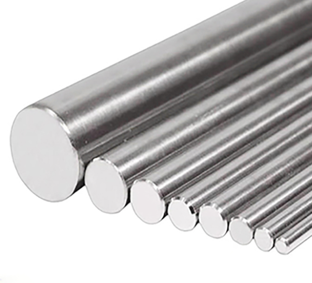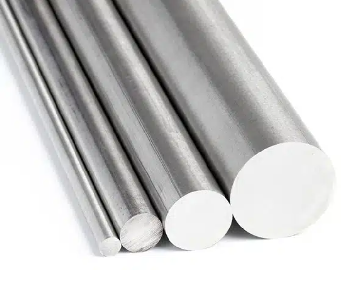

How to Select Alloy Bars for Metering Pump Shafts and Chemical Pump Components
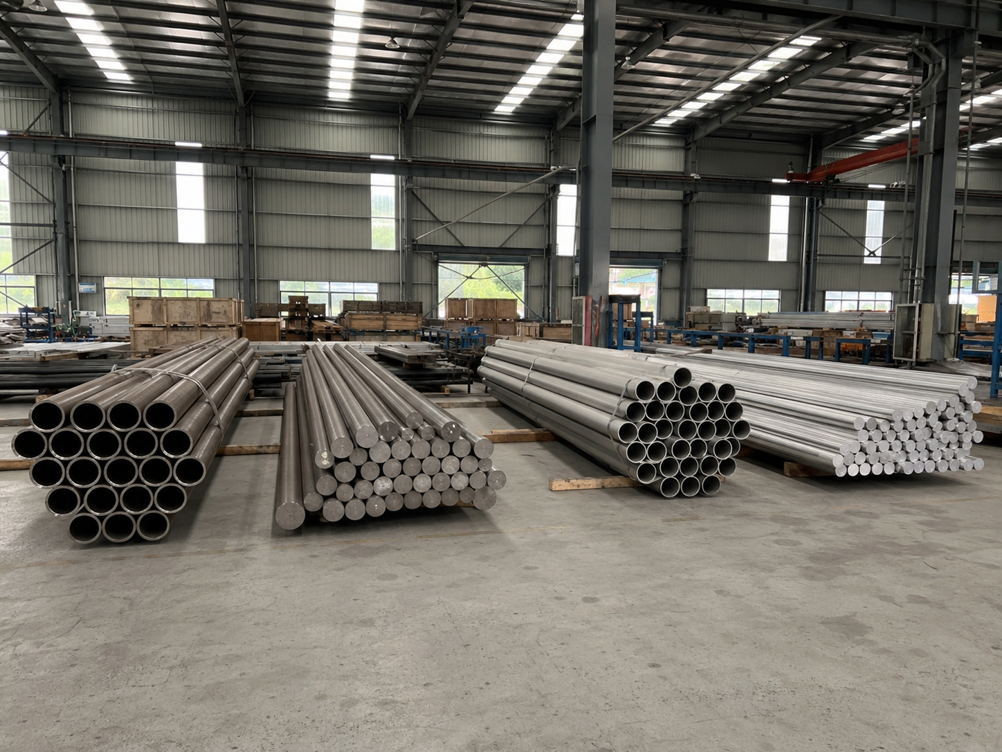
Selecting alloy bars for metering pump shafts and chemical pump components requires more than choosing the grade with the highest strength or the most impressive corrosion-resistance description.
A pump shaft may need to transmit torque while resisting bending, vibration, fatigue, wear, and a corrosive liquid. A metering-pump plunger may face pulsating pressure, packing contact, surface wear, and direct chemical exposure. A valve stem or check-valve component may experience impact, galling, deposits, and repeated opening cycles.
At the same time, not every pump shaft is directly exposed to the process liquid. In a hydraulic diaphragm metering pump, the diaphragm separates much of the drive mechanism from the chemical. In a packed plunger design, the plunger, packing interface, check valves, and liquid-end components may be more chemically critical than the drive shaft.
The correct alloy bar is therefore the material, condition, size, surface, inspection level, and documentation package that match the exact pump type, component function, process medium, mechanical load, manufacturing route, and maintenance strategy.
The first question should not be:
“Which alloy is best for chemical pump shafts?”
It should be:
“What must this particular component resist, and which requirements must be provided by the raw bar, the finished component, the pump design, and the operating system?”
First Identify the Pump Type and Component
“Metering pump” and “chemical pump” describe broad equipment categories.
The loads, wetted parts, operating behavior, and material requirements can differ considerably.
API 675 controlled-volume pump requirements provide one framework for certain hydraulically actuated diaphragm and packed-plunger controlled-volume pumps used in petroleum, chemical, and gas services. The applicable standard, edition, customer specification, and pump design should always be confirmed for the actual project.
Common Pump and Component Categories
| Pump or Component | Typical Function | Important Material Questions |
|---|---|---|
| Hydraulic diaphragm metering pump | Meters fluid while a diaphragm separates the process side from the hydraulic drive | Which liquid-end parts are wetted, and does the drive shaft contact the process? |
| Packed plunger metering pump | Uses a reciprocating plunger through packing to displace the liquid | Chemical resistance, surface finish, wear, hardness, reciprocating fatigue and packing compatibility |
| Centrifugal chemical pump | Transfers liquid through a rotating impeller | Radial and axial loads, shaft deflection, cavitation, seal design, corrosion and erosion |
| Sealless magnetic-drive pump | Transfers torque through magnetic coupling without a conventional shaft seal | Containment shell, internal bearings, shaft or spindle, magnetic materials, heat generation and dry-running risk |
| Rotary positive-displacement pump | Uses gears, screws, lobes or another rotating displacement mechanism | Sliding contact, viscosity, galling, wear, clearances and torque |
| Pump shaft | Transmits torque and supports rotating components | Strength, stiffness, fatigue, straightness, surface, runout and corrosion |
| Plunger | Reciprocates through packing or a seal | Surface finish, hardness, wear, chemical exposure and dimensional stability |
| Shaft sleeve | Protects a shaft at a wetted or sealing location | Crevice risk, fit, galling, coating or sleeve integrity and replaceability |
| Valve stem or check-valve part | Controls one-way or regulated liquid movement | Impact, wear, deposits, chemical compatibility and galling |
| Pins, tie rods and fasteners | Retain or connect components | Preload, corrosion, fatigue, SCC and galvanic compatibility |
The component should also be classified as:
- Fully wetted;
- intermittently wetted;
- protected by a sleeve;
- exposed only to leakage or vapor;
- completely isolated from the process.
A non-wetted drive shaft and a directly wetted plunger should not automatically use the same material.
Which Pump Components Are Normally Made from Bar?
“Alloy bar” is not the correct raw-material form for every pump component.
Bars may be machined into:
- Shafts;
- plungers;
- piston rods;
- valve stems;
- spindles;
- pins;
- tie rods;
- fasteners;
- couplings;
- shaft sleeves;
- small wear components;
- check-valve components.
Pump casings and impellers may instead be manufactured from:
- Castings;
- forgings;
- plate;
- welded fabrication;
- molded polymers;
- ceramics;
- lined or clad structures.
The product form matters because casting, forging, bar production, heat treatment, microstructure, sampling and inspection requirements are different.
A corrosion chart for a plate alloy does not automatically establish that a bar in another heat-treatment condition has identical mechanical or manufacturing behavior.
Define the Complete Process Medium
Chemical compatibility cannot be established from a general name such as:
- Sulfuric acid;
- hydrochloric acid;
- caustic;
- chloride solution;
- solvent;
- slurry;
- wastewater;
- dosing chemical.
Buyers should define the full operating composition.
Medium Information to Confirm
| Process Variable | Why It Matters |
|---|---|
| Main chemical | Establishes the basic corrosion environment |
| Concentration range | Dilute and concentrated conditions may behave differently |
| Minimum and maximum temperature | Corrosion, strength, viscosity and vapor pressure change with temperature |
| pH and redox condition | Influence passive-film stability and corrosion mechanism |
| Chloride, fluoride and other halides | May increase localized-corrosion risk in susceptible alloys |
| Dissolved gases | Oxygen, chlorine, hydrogen sulfide and other gases may change corrosion |
| Trace impurities | Small contaminant levels can control corrosion |
| Solids | Affect abrasion, erosion, blockage and seal wear |
| Particle size and hardness | Influence slurry wear |
| Density | Affects pump power and mechanical loading |
| Viscosity | Changes pump performance, flow behavior and power demand |
| Vapor pressure | Influences NPSH and cavitation |
| Gas or bubbles | Affect hydraulic stability and erosion |
| Cleaning chemicals | May be more aggressive than the normal process |
| Startup and shutdown | Dilution, air ingress, stagnation and condensation can change the environment |
| Expected process upsets | Temporary high temperature or contamination may govern selection |
For mixed-media applications, see the related guide on material selection for mixed chemical media.
Fluid Properties Affect Both Corrosion and Shaft Loading
Pump performance data are commonly generated using water under stated reference conditions. When the process liquid has a different density or viscosity, the required input power, efficiency, pressure behavior, flow and mechanical loading may change.
This matters because the shaft is selected for the actual pump duty—not only the nominal motor rating.
Important inputs include:
- Maximum absorbed power;
- starting torque;
- normal and upset torque;
- rotational speed;
- reciprocating frequency;
- fluid density;
- viscosity;
- solids;
- pressure pulsation;
- maximum differential pressure;
- hydraulic radial and axial thrust;
- expected starts and stops.
The shaft design should also consider the actual operating region of the pump.
Running a centrifugal pump far from its preferred operating region can increase hydraulic imbalance, vibration, recirculation and shaft loading. Insufficient NPSH margin can produce cavitation, performance loss, noise and damage.
Hydraulic Institute guidance on NPSH and cavitation explains why operating region and NPSH margin are part of pump reliability.
A stronger shaft material cannot correct:
- Insufficient suction pressure;
- an incorrectly sized pump;
- severe cavitation;
- chronic misalignment;
- inadequate bearing support;
- excessive shaft deflection;
- poor foundation stiffness;
- operation at shutoff or runout.
Map the Mechanical Loads on the Component
Torsional Load
A rotating shaft transmits motor torque to the pump element.
The design should consider:
- Steady torque;
- start-up torque;
- torque spikes;
- jams or blocked flow;
- variable-speed operation;
- coupling behavior;
- keyways or splines.
High tensile strength alone does not prove adequate torsional fatigue performance.
Bending Load
Pump shafts may bend because of:
- Radial hydraulic force;
- impeller overhang;
- coupling misalignment;
- bearing span;
- shaft weight;
- unbalanced rotating components;
- piping strain;
- uneven seal forces.
Excessive shaft deflection can affect:
- Mechanical seals;
- packing;
- bearings;
- wear rings;
- impeller clearance;
- vibration;
- fatigue life.
Elastic modulus and shaft geometry may be as important as yield strength.
Axial Load
Axial thrust may be generated by:
- Pressure difference;
- impeller geometry;
- hydraulic imbalance;
- reciprocating operation;
- pressure pulsation;
- check-valve behavior.
The shaft, thrust bearing, shoulders and retaining features must be evaluated as a system.
Cyclic and Fatigue Load
Pump components rarely experience one perfectly constant stress.
Cyclic loading can result from:
- Rotation;
- pressure pulsation;
- reciprocation;
- vibration;
- startup and shutdown;
- cavitation;
- flow instability;
- misalignment;
- repeated seal contact.
Fatigue resistance depends on more than alloy grade. It can also be affected by:
- Heat treatment;
- surface roughness;
- grinding direction;
- residual stress;
- keyways;
- threads;
- shoulders;
- corrosion pits;
- inclusions;
- component diameter;
- final machining.
The fatigue performance of a polished laboratory specimen should not be applied directly to a machined shaft without understanding these differences.
Corrosion and Mechanical Stress Must Be Evaluated Together
Uniform Corrosion
Uniform corrosion may cause relatively even material loss.
For a shaft, even moderate uniform loss can affect:
- Diameter;
- balance;
- seal contact;
- packing compression;
- surface finish;
- fatigue strength.
A corrosion allowance that is acceptable for a thick vessel wall may not be acceptable for a precision shaft or plunger.
Pitting and Crevice Corrosion
A small pit can become a fatigue-crack initiation site.
Potential crevice locations include:
- Shaft sleeves;
- keys;
- threads;
- retaining rings;
- seal interfaces;
- packing;
- deposits;
- stagnant gaps.
A shaft material should not be approved only from an average corrosion rate.
Stress Corrosion Cracking
SCC requires a susceptible material, a relevant environment and tensile stress.
Tensile stress may be introduced through:
- Applied torque or bending;
- machining;
- grinding;
- cold work;
- heat treatment;
- press fits;
- threads;
- welding;
- residual stress.
A high room-temperature tensile result on an MTR does not prove resistance to SCC.
Corrosion Fatigue
A pump shaft may experience mechanical cycling while exposed to a corrosive medium.
Corrosion can reduce fatigue life by:
- Initiating pits;
- attacking surface defects;
- preventing stable crack closure;
- accelerating crack growth.
A material that performs well in air may behave differently in the actual pumped fluid.
Galvanic Corrosion
Pump assemblies often contain different materials:
- Shaft;
- sleeve;
- impeller;
- casing;
- fasteners;
- seal hardware;
- bearings;
- coatings.
Where electrically connected dissimilar materials contact a conductive liquid, galvanic effects may need to be assessed.
Surface-area ratio, electrolyte, coating condition and joint design all matter.
Cavitation, Erosion and Abrasion Are Not the Same Problem
Cavitation Erosion
Cavitation occurs when local liquid pressure falls sufficiently for vapor cavities to form and later collapse.
The collapse can damage:
- Impeller surfaces;
- casing waterways;
- valve components;
- nearby seals and bearings through increased vibration.
ASTM G32 cavitation erosion testing provides a standardized method for comparing material damage under one controlled cavitation condition.
A laboratory ranking does not reproduce every pump liquid, pressure, velocity, surface finish or geometry.
Solid-Particle Erosion
Particles may strike components at different:
- Velocities;
- angles;
- concentrations;
- sizes;
- shapes;
- hardness levels.
Wear may be especially severe at:
- Impeller leading edges;
- volutes;
- elbows;
- valves;
- throttling points;
- injection nozzles.
Abrasion
Abrasive particles can slide or rub against:
- Plungers;
- packing;
- sleeves;
- bushings;
- close-clearance components.
Hardness can be useful, but it is not a complete predictor of service life.
AMPP erosion-corrosion guidance cautions that high hardness alone does not guarantee high erosion-corrosion resistance and that equipment design is also important.
Corrosion–Wear Synergy
Wear can remove a protective film, after which corrosion accelerates. Corrosion may then soften or roughen the surface, increasing wear.
The combined loss can be greater than the simple sum of corrosion and mechanical wear measured separately.
Surface Finish Matters for Shafts and Plungers
The surface of a raw bar is not necessarily the final functional surface.
The finished component may require controlled:
- Diameter;
- roundness;
- straightness;
- runout;
- cylindricity;
- surface roughness;
- grinding direction;
- hardness;
- coating thickness;
- absence of grinding burns;
- edge radii.
For a plunger or packing-contact shaft, surface finish affects:
- Leakage;
- packing wear;
- friction;
- heat generation;
- seal life;
- chemical retention in surface valleys.
For a fatigue-sensitive shaft, deep machining marks and sharp transitions can become crack-initiation locations.
The RFQ should distinguish:
- Raw hot-worked bar;
- peeled or turned bar;
- ground bar;
- finished shaft or plunger.
A bar supplier should not be assumed to provide finished-component tolerances unless these are specifically ordered.
Solid Alloy, Sleeve, Coating or Hybrid Construction?
A solid high-alloy shaft is not the only possible design.
Solid Alloy Shaft
Possible advantages:
- Continuous composition;
- no sleeve interface;
- easier material traceability.
Possible limitations:
- High material cost;
- difficult machining;
- unnecessary use of corrosion-resistant material in non-wetted areas.
Shaft with Replaceable Sleeve
Possible advantages:
- Stronger or lower-cost shaft core;
- replaceable wetted or seal-contact surface;
- localized use of corrosion-resistant material.
Possible limitations:
- Crevice corrosion;
- fit and fretting;
- leakage under the sleeve;
- galvanic interaction;
- sleeve movement;
- difficult inspection.
Coated Shaft or Plunger
Possible advantages:
- Improved hardness;
- wear resistance;
- reduced friction;
- selective surface protection.
Possible limitations:
- Pores;
- cracks;
- delamination;
- edge damage;
- substrate corrosion;
- thermal-expansion mismatch;
- repair difficulty.
Ceramic or Non-Metallic Components
Possible advantages:
- High hardness;
- chemical resistance;
- low metal-ion contamination.
Possible limitations:
- Brittleness;
- impact sensitivity;
- joining;
- thermal shock;
- dimensional and inspection challenges.
The complete shaft–sleeve–seal–medium system should be evaluated rather than selecting each material independently.
How to Screen Candidate Alloy Families
The following comparison is a screening framework, not an application-approval table.
Austenitic Stainless Steels
Potential advantages:
- Broad availability;
- good machinability and fabrication;
- lower cost;
- established pump use in moderate services.
Important limitations:
- Localized corrosion in aggressive halide environments;
- SCC under susceptible conditions;
- lower strength than duplex or precipitation-hardened grades;
- application-dependent wear resistance.
316L may be suitable for many services, but it should not be dismissed or approved based only on its common use.
Duplex and Super Duplex Stainless Steels
Potential advantages:
- Higher strength than common austenitic stainless steels;
- useful chloride resistance in suitable environments;
- possible reduction in shaft diameter where design permits.
Important limitations:
- Phase balance and heat treatment;
- welding limitations;
- temperature restrictions;
- localized-corrosion and SCC limits;
- not universally compatible with strong acids or mixed chemicals.
Nickel-Chromium-Molybdenum Alloys
Materials such as UNS N10276 and N06022 may be evaluated for aggressive or variable chemical environments.
Potential advantages:
- Broad corrosion-resistance capability in many chemical services;
- availability as bar under standards such as ASTM B574 nickel alloy bar requirements.
Important limitations:
- Individual grades are not interchangeable;
- high cost;
- lower strength than some precipitation-hardened alloys;
- machining complexity;
- actual medium, temperature, wear and shaft design still need verification.
A corrosion-resistant alloy may still require a larger shaft diameter if its mechanical properties are lower than another candidate.
Alloy 625
UNS N06625 bar may be supplied under ASTM B446 Alloy 625 bar requirements.
It may be evaluated where a project requires a combination of:
- Corrosion resistance;
- mechanical strength;
- fabrication;
- elevated-temperature capability.
It should not be treated as a universal chemical-pump shaft material.
Nickel-Copper Alloys
Nickel-copper bar products may fall under ASTM B164 nickel-copper alloy bars.
Their suitability depends on:
- Exact medium;
- oxidizing contaminants;
- temperature;
- velocity;
- aeration;
- mechanical requirements;
- galvanic connections.
The commercial name alone is not enough for approval.
Precipitation-Hardened Nickel Alloys
High-strength nickel alloys such as Alloy 718 may be supplied under standards including ASTM B637 precipitation-hardened nickel bars.
Potential advantages:
- High strength;
- fatigue capability in properly processed conditions;
- elevated-temperature strength in applicable services.
Important limitations:
- Heat treatment must be controlled;
- high strength does not prove optimum corrosion resistance;
- machining and residual stress require attention;
- may be unnecessary for many chemical-pump applications.
Alloy 718 should be chosen because the mechanical and environmental requirements justify it—not simply because it is stronger.
Titanium Grades
Titanium bars may be supplied under ASTM B348 titanium bar requirements.
Potential advantages:
- Low density;
- corrosion resistance in selected passive environments;
- useful strength-to-weight performance in certain grades.
Important limitations:
- Compatibility depends on passive-film stability;
- reducing acids, fluorides and high-temperature crevices require careful review;
- titanium can gall at sliding or threaded interfaces;
- hydrogen-related effects may require evaluation;
- low elastic modulus can influence shaft deflection;
- Grade 2, Grade 7 and Grade 5 have different mechanical and corrosion characteristics.
Grade 2 or Grade 7 should not be selected solely because the fluid contains chlorides.
Martensitic and Precipitation-Hardened Stainless Steels
Potential advantages:
- High strength;
- hardness;
- machinability in selected conditions;
- established shaft use in non-aggressive environments.
Important limitations:
- Corrosion resistance may be lower than nickel alloys, titanium or duplex grades;
- heat treatment and hardness affect SCC and toughness;
- unsuitable for many directly wetted aggressive chemical services.
They may be appropriate for isolated drive shafts but unsuitable for wetted components.
Match the Alloy to the Component Function
| Component | Primary Requirements | Common Selection Mistake |
|---|---|---|
| Rotating shaft | Torque, bending, fatigue, stiffness, straightness, corrosion | Selecting only by tensile strength |
| Metering plunger | Chemical resistance, surface, hardness, wear, reciprocating fatigue | Ignoring packing contact and surface finish |
| Shaft sleeve | Corrosion, wear, fit, replaceability, crevice control | Assuming the sleeve completely protects the shaft |
| Valve stem | Chemical resistance, galling, impact, deposits | Ignoring sliding contact and localized wear |
| Check-valve ball or seat | Chemical resistance, hardness, impact, sealing | Choosing bar material without reviewing seat pairing |
| Pin or pivot | Shear, fatigue, wear, corrosion | Ignoring lubrication and fretting |
| Tie rod or fastener | Preload, fatigue, SCC, external atmosphere | Selecting by wetted-fluid corrosion chart only |
| Magnetic-drive spindle | Corrosion, bearing interface, stiffness, heat | Ignoring dry-running and internal bearing conditions |
What Should Be Specified on the Bar RFQ?
Material Definition
- Alloy grade;
- UNS designation;
- product standard;
- specification revision;
- product form;
- heat-treatment condition;
- hot-worked, cold-worked, peeled or ground condition.
Dimensions
- Diameter;
- length;
- diameter tolerance;
- straightness;
- roundness;
- machining allowance;
- end condition;
- minimum usable length.
Mechanical and Metallurgical Requirements
- Tensile properties;
- yield strength;
- elongation;
- hardness;
- impact properties where required;
- grain or microstructure requirements where applicable;
- heat-treatment record;
- orientation and sampling requirements.
Inspection
- Visual inspection;
- dimensional inspection;
- straightness;
- surface condition;
- PMI;
- ultrasonic testing where required;
- acceptance level and coverage;
- third-party inspection;
- test-report review before shipment.
Traceability and Documents
- Heat number;
- piece marking;
- original mill MTR;
- supplier CoC;
- EN 10204 document type where required;
- heat-treatment certificate;
- NDT report;
- dimensional report;
- approved deviations;
- packing list linked to heat numbers.
The applicable revision should be defined in the purchase order rather than assumed from the alloy name.
What Does an MTR Prove?
An MTR or MTC may show:
- Alloy grade;
- heat number;
- chemical composition;
- mechanical properties;
- heat-treatment condition;
- product standard;
- selected inspection results.
It does not normally prove:
- Compatibility with the actual pumped fluid;
- shaft fatigue life;
- cavitation resistance;
- slurry wear life;
- final shaft straightness after machining;
- finished surface roughness;
- seal performance;
- pump reliability;
- absence of every possible internal discontinuity.
BS EN 10204 inspection documents define types of inspection documents for metallic products. The document type still needs to be read together with the product standard and purchase order.
ISO 9001 Is Not a Pump-Shaft Approval
ISO 9001 supply-chain guidance explains that buyers should clearly define their technical needs through specifications, drawings and relevant standards.
ISO 9001 can support confidence that a supplier manages its quality processes systematically.
It does not specify:
- The correct alloy;
- shaft dimensions;
- heat treatment;
- corrosion resistance;
- UT coverage;
- fatigue life;
- application suitability.
Why Laboratory Scope Matters
ISO/IEC 17025 laboratory competence addresses the competence, impartiality and consistent operation of testing and calibration laboratories.
When third-party testing is required, buyers should verify:
- Laboratory identity;
- accreditation body;
- certificate validity;
- scope of accreditation;
- exact test method;
- sample identity;
- sampling responsibility;
- test standard and revision;
- report approval.
A laboratory may be accredited while a particular corrosion, fatigue, wear, metallographic or ultrasonic method is outside its accredited scope.
A Risk-Based Material Selection Process
Step 1: Identify the Pump and Component
Confirm:
- Pump type;
- component function;
- wetted or non-wetted status;
- rotational or reciprocating operation;
- bar, casting, forging or other product form.
Step 2: Define the Full Medium
Include:
- composition;
- concentration;
- temperature;
- impurities;
- solids;
- density;
- viscosity;
- vapor pressure;
- cleaning and upset conditions.
Step 3: Define the Hydraulic Duty
Confirm:
- flow;
- suction condition;
- differential pressure;
- NPSH;
- speed;
- power;
- operating range;
- pressure pulsation.
Step 4: Map Mechanical Loads
Review:
- torque;
- bending;
- axial thrust;
- radial thrust;
- fatigue;
- vibration;
- impact;
- keyways;
- threads;
- shaft shoulders.
Step 5: Identify Damage Mechanisms
Possible mechanisms include:
- uniform corrosion;
- pitting;
- crevice corrosion;
- SCC;
- corrosion fatigue;
- cavitation;
- slurry erosion;
- abrasion;
- galling;
- fretting;
- galvanic corrosion.
Step 6: Compare Construction Options
Compare:
- solid alloy;
- sleeve;
- coating;
- clad design;
- ceramic;
- polymer;
- replaceable wear component.
Step 7: Screen Candidate Materials
Compare:
- mechanical strength;
- modulus;
- corrosion;
- fatigue;
- wear;
- machinability;
- heat treatment;
- product availability;
- inspection;
- lead time.
Step 8: Define the Evidence Package
Specify:
- product standard;
- MTR;
- heat traceability;
- dimensions;
- straightness;
- PMI;
- NDT;
- additional testing;
- third-party inspection.
Step 9: Validate the Finished Component
Raw-bar compliance does not replace:
- finished-dimensional inspection;
- surface inspection;
- runout measurement;
- balance;
- component NDT;
- pump test;
- pressure test;
- vibration verification.
Common Mistakes When Ordering Pump-Shaft Alloy Bars
1. Ordering Only by Alloy Name
“C276 bar” or “titanium bar” does not define the standard, condition, dimensions, straightness, surface or inspection.
2. Assuming Every Shaft Is Wetted
The drive shaft may be isolated while the plunger, valve or sleeve is directly exposed.
3. Using Corrosion Data Without Mechanical Review
A highly corrosion-resistant alloy may lack the strength or stiffness needed for the existing shaft geometry.
4. Choosing the Strongest Alloy Without Corrosion Review
A high-strength precipitation-hardened alloy may not provide the best resistance to the actual process medium.
5. Treating Hardness as Wear Life
Particle velocity, angle, cavitation, deposits and corrosion can be more important than hardness alone.
6. Ignoring Straightness and Machining Allowance
A chemically correct bar can still be unsuitable for a long precision shaft if straightness, surface or stock allowance is inadequate.
7. Ignoring Keyways and Threads
These features concentrate stress and may become fatigue or corrosion-initiation locations.
8. Ignoring Cavitation
A material upgrade cannot correct insufficient NPSH or an unsuitable pump operating point.
9. Treating the MTR as Final Component Approval
The MTR describes the supplied batch, not the finished shaft or complete pump.
10. Treating ISO 9001 as Product Certification
The quality-management certificate does not define the ordered material properties.
11. Specifying UT Without a Standard or Acceptance Level
“100% UT” does not define sensitivity, calibration, coverage or acceptance criteria.
12. Selecting the Highest-Cost Material to Minimize Risk
Over-specification may add machining, lead-time, supply and maintenance risks without solving the governing problem.
RFQ Checklist for Metering Pump Shafts and Chemical Pump Parts
Before requesting a quotation, provide:
- Pump type;
- pump manufacturer or model where available;
- component name;
- component drawing;
- wetted or non-wetted status;
- fluid composition;
- concentration range;
- impurities;
- solids content;
- particle size and hardness;
- density;
- viscosity;
- vapor pressure;
- operating temperature;
- design temperature;
- suction pressure;
- discharge pressure;
- differential pressure;
- flow rate;
- rotational speed or stroke frequency;
- absorbed power;
- starting torque;
- pressure pulsation;
- NPSH conditions;
- startup and shutdown frequency;
- expected operating hours;
- vibration requirements;
- shaft span and bearing arrangement;
- seal or packing interface;
- corrosion mechanism of concern;
- wear or cavitation concern;
- alloy grade;
- UNS designation;
- ASTM, ASME, EN or project standard;
- specification revision;
- heat-treatment condition;
- bar diameter;
- length;
- diameter tolerance;
- straightness;
- roundness;
- machining allowance;
- surface condition;
- hardness requirement;
- mechanical-property requirement;
- UT method and acceptance level;
- PMI requirement;
- dimensional report;
- MTR/MTC;
- EN 10204 document type;
- heat-number marking;
- third-party inspection;
- corrosion or wear testing;
- packaging;
- deviation approval;
- record-retention requirement.
Frequently Asked Questions
What is the best alloy for a chemical pump shaft?
There is no universal best alloy. The decision depends on whether the shaft is wetted, the process chemistry, temperature, torque, bending, fatigue, stiffness, wear, shaft geometry and manufacturing requirements.
Is Hastelloy C276 always suitable for corrosive pump shafts?
No. UNS N10276 may be a strong corrosion-resistant candidate, but its mechanical properties, actual medium, temperature, wear, shaft size, fatigue and cost must be reviewed.
Is Alloy 718 better because it has higher strength?
Not automatically. Alloy 718 may provide high strength in an appropriate heat-treated condition, but it may not offer the best chemistry-specific corrosion resistance. High strength and chemical compatibility must be evaluated separately.
Can titanium be used for pump shafts?
Titanium may be suitable for selected environments and can reduce component mass, but its passive-film stability, grade, modulus, galling behavior, crevice condition, fluorides, reducing media and mechanical design must be reviewed.
Is 316L unsuitable for all chemical pumps?
No. It remains suitable for many moderate services. It becomes unsuitable when the actual medium, temperature, chlorides, stress or localized-corrosion risk exceeds its capability.
Does higher hardness mean better slurry-pump life?
Not necessarily. Wear also depends on particle size, concentration, velocity, impact angle, cavitation, corrosion and component geometry.
Does an MTR prove that the shaft will perform reliably?
No. It supports batch identity and product-standard compliance. Finished-shaft performance also depends on design, machining, surface, loads, assembly, pump operation and maintenance.
Should every pump-shaft bar receive UT?
Only when required by the product standard, drawing, criticality assessment or purchase order. The method, coverage, sensitivity and acceptance criteria must be defined.
Can a sleeve allow a lower-cost shaft material?
Sometimes. A sleeve can separate mechanical and corrosion requirements, but fit, crevice corrosion, leakage, fretting, galvanic effects and replaceability must be assessed.
Who should approve the final material?
Final approval should involve the pump manufacturer or designer, process engineer, corrosion or materials specialist, mechanical engineer, quality team and end user.
Conclusion
Selecting alloy bars for metering pump shafts and chemical pump components is not a simple ranking of corrosion resistance, tensile strength or price.
A reliable decision must connect:
- Pump type;
- component function;
- wetted status;
- complete process chemistry;
- fluid density, viscosity and vapor pressure;
- torque, bending and thrust;
- fatigue and vibration;
- shaft stiffness and geometry;
- pitting, crevice corrosion and SCC;
- cavitation, erosion and abrasion;
- seal and packing contact;
- surface finish and straightness;
- product standard and heat treatment;
- batch documentation and inspection;
- finished-component validation;
- pump operating conditions.
Nickel-chromium-molybdenum alloys, Alloy 625, precipitation-hardened nickel alloys, nickel-copper alloys, titanium, duplex stainless steels, common stainless steels, sleeves, coatings and non-metallic systems can all be appropriate under different conditions.
The strongest or most expensive bar is not automatically the most reliable choice.
The objective is to select a material and manufacturing route that provide adequate corrosion resistance, mechanical performance, dimensional control, inspectability and traceability for the specific pump component—while ensuring that hydraulic design, machining, assembly and operating conditions are controlled as part of the same reliability strategy.