
| Item | Details | ||||||||||||||||||||||||||||||
|---|---|---|---|---|---|---|---|---|---|---|---|---|---|---|---|---|---|---|---|---|---|---|---|---|---|---|---|---|---|---|---|
| Page Purpose and Product Position |
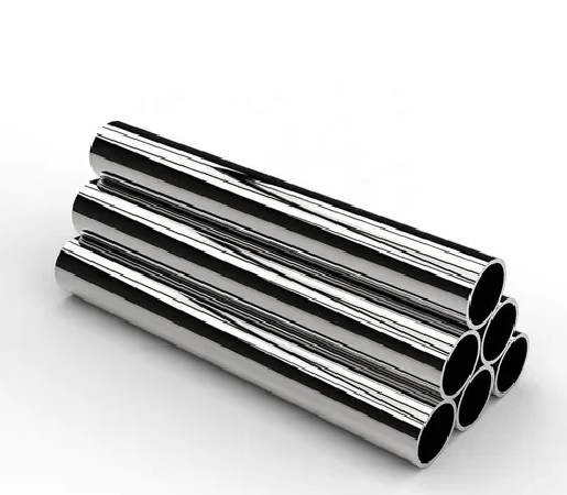
This page focuses on Alloy 825 heat exchanger and condenser tubes supplied as straight seamless or welded tubing, with U-bend processing reviewed when the project specification permits it. For general Alloy 825 seamless pipe, welded pipe, process piping, and broader tubular procurement, see the Alloy 825 Pipe & Tube main product page. Tube sheets, baffles, support rods, plate, bar, and finished heat exchanger assemblies are separate product forms and are not automatically covered by a heat exchanger tube specification. |
||||||||||||||||||||||||||||||
| Material Identification |
1. Material: Alloy 825. 2. UNS Designation: UNS N08825. 3. Werkstoff Number: W.Nr. 2.4858. 4. Alloy Type: Titanium-stabilized nickel-iron-chromium-molybdenum-copper alloy. 5. Product Form: Heat exchanger, condenser, evaporator, cooler, and project-specific tubing. 6. Commercial Name: Alloy 825. “INCOLOY®” is a registered trade name and should not replace the UNS number and governing material standard in a purchase order. |
||||||||||||||||||||||||||||||
| Primary Heat Exchanger Tube Standards |
The RFQ should state the exact standard, edition, seamless or welded construction, grade, OD, wall basis, length, condition, inspection, documentation, and supplementary requirements. ASTM B423, B163, and B704 are not interchangeable merely because all may include UNS N08825. |
||||||||||||||||||||||||||||||
| Chemical Composition (Weight %) |
Reference limits for UNS N08825. Final acceptance follows the governing product standard and heat-specific MTR/MTC.
The reported chemistry must be traceable to the supplied heat or lot. A generic composition table is not a substitute for batch-specific certification. |
||||||||||||||||||||||||||||||
| Mechanical and Physical Property Direction |
Mechanical acceptance depends on the ordered standard, tube construction, condition, wall thickness, diameter, and test specimen. Commonly referenced annealed Alloy 825 values include approximately 586 MPa minimum tensile strength, 241 MPa minimum 0.2% yield strength, and 30% minimum elongation. These figures are reference values only; the final purchase requirement must follow ASTM B163, ASTM B704, ASTM B423, or the project specification.
Elevated-temperature strength, fatigue, creep, impact, hardness, and corrosion properties should not be presented as universal tube acceptance values unless the exact test and condition are specified. |
||||||||||||||||||||||||||||||
| Why Alloy 825 Is Considered for Heat Exchanger Tubes |
Alloy 825 is commonly evaluated where a heat exchanger combines reducing-acid exposure, oxidizing contaminants, chlorides, localized-corrosion risk, or sour-process conditions. Its nickel content supports resistance to chloride-ion stress-corrosion cracking. Molybdenum and copper contribute to performance in selected reducing environments such as sulfuric and phosphoric acids. Chromium supports resistance in oxidizing media, while titanium stabilization helps control sensitization when the alloy receives the appropriate thermal treatment. These advantages are environment-specific. Alloy 825 is not automatically the best choice for every seawater, nitric-acid, hydrochloric-acid, high-temperature, or mixed-chemical heat exchanger. |
||||||||||||||||||||||||||||||
| Application Screening Matrix |
|
||||||||||||||||||||||||||||||
| Available Heat Exchanger Tube Forms |
Supply can be reviewed for: 1. Straight seamless condenser and heat-exchanger tubes. 2. Straight welded heat-exchanger and condenser tubes. 3. Fixed-length tubes and project-specific cut lengths. 4. U-bend tubes when the required bend radius, tangent length, wall thinning, ovality, heat treatment, and inspection are defined. 5. Cooler, evaporator, condenser, heater, and reboiler tubing. 6. Sample tubes, first-article quantities, and project production quantities subject to MOQ and mill capability. 7. Pickled, descaled, bright, polished, or other agreed surface conditions. Tube sheets, baffles, support plates, solid rods, and complete bundles require separate product specifications and quotations. |
||||||||||||||||||||||||||||||
| Dimensions, Wall Basis, and Tolerances |
1. Specify outside diameter, wall thickness, length, and quantity. 2. State whether the tube is ordered on an average-wall or minimum-wall basis when applicable. 3. Confirm seamless or welded construction before comparing dimensions and prices. 4. OD, wall, ovality, straightness, cut length, end condition, and surface tolerances follow the governing standard unless tighter values are agreed in writing. 5. Tighter tolerances require review of manufacturing route, tube size, wall, length, condition, measurement method, sampling, yield, cost, and lead time. 6. Do not use generic promises such as ±0.02 mm, 12 m maximum length, or fixed straightness values for every size without confirming production capability. |
||||||||||||||||||||||||||||||
| U-Bend Tube Requirements |
U-bend orders should define: 1. ASTM or project tube standard. 2. Tube OD, wall basis, straight-leg length, tangent length, and bend radius. 3. Bend orientation, bundle position, leg identification, and dimensional drawing. 4. Maximum ovality and wall thinning at the bend. 5. Heat-treatment requirement before or after bending. 6. Surface condition, cleanliness, and contamination controls. 7. Eddy-current, hydrostatic, pneumatic, dimensional, dye-penetrant, or other post-bend inspection. 8. Packaging supports that prevent bend distortion and tube-to-tube damage. No universal minimum bend radius, wall-thinning limit, or exemption from post-bend heat treatment should be assumed without the controlling specification and bend qualification. |
||||||||||||||||||||||||||||||
| Tube-to-Tubesheet Compatibility |
Tube material selection should be reviewed together with the tubesheet and joint design. Important factors include: 1. Tubesheet alloy, cladding, or weld-overlay material. 2. Galvanic coupling and wetted area ratio. 3. Mechanical expansion, groove geometry, seal welding, or strength welding. 4. Tube hardness, wall thickness, and allowable expansion. 5. Differential thermal expansion and thermal cycling. 6. Crevice formation at the tube-to-tubesheet joint. 7. Welding filler, heat input, cleaning, and inspection. 8. Repair and retubing procedure. For a broader selection workflow, see How to Select Compatible Tube and Tubesheet Materials for Heat Exchangers. |
||||||||||||||||||||||||||||||
| Surface Condition, Cleanliness, and Fouling |
Available surfaces can be reviewed as annealed and pickled, descaled, polished, or project-specific finishes where technically feasible. The RFQ should state: 1. Internal and external surface requirements. 2. Roughness requirement and measurement method, when applicable. 3. Limits for scale, pits, seams, scratches, laps, oxide, staining, and handling marks. 4. Cleaning, degreasing, chloride, sulfur, lead, zinc, iron-contamination, or high-purity controls. 5. Whether mechanical polishing or another finish is required for cleanability or fouling control. A polished or electropolished surface does not make Alloy 825 universally suitable for pharmaceutical, semiconductor, or food service. Cleanability, fabrication, regulatory, and contamination requirements must be reviewed separately. |
||||||||||||||||||||||||||||||
| Welding and Fabrication |
Alloy 825 can be welded and fabricated using qualified procedures suitable for nickel-iron-chromium alloys. Controls should address: 1. Joint cleanliness and protection from sulfur, lead, zinc, oils, marking compounds, and other contaminants. 2. Approved filler metal and welding process. 3. Heat input, interpass temperature, shielding, purge, and joint geometry. 4. Weld and heat-affected-zone inspection. 5. Post-weld cleaning and oxide removal. 6. Any heat-treatment requirement from the governing material, fabrication, or project specification. Material supplied to ASTM B163 or B704 does not by itself qualify the completed tube-to-tubesheet joint or finished heat exchanger. |
||||||||||||||||||||||||||||||
| Eddy-Current and Nondestructive Testing |
Testing should follow the ordered tube standard and purchase specification. Available inspection can include: 1. Eddy-current or another nondestructive electric test. 2. Hydrostatic or pneumatic testing where required or permitted. 3. Ultrasonic testing when the method is suitable for the size and product. 4. Dye-penetrant examination for specified surfaces, welds, or formed regions. 5. PMI for alloy identity verification. 6. Visual and dimensional inspection. 7. Third-party witness or review at agreed hold points. An ET statement should define the standard, calibration tube, artificial discontinuity, frequency, coverage, speed, signal threshold, and acceptance criteria. “100% ET,” “5% wall sensitivity,” or a fixed defect size should not be promised unless the governing order defines those requirements and the process is qualified. |
||||||||||||||||||||||||||||||
| Pressure and Leak Testing |
Hydrostatic, pneumatic, leak, or nondestructive electric testing must follow the product standard and order requirements. The buyer should confirm: 1. Whether hydrostatic testing or an allowed alternative is required. 2. Test-pressure calculation and applicable code or standard. 3. Test medium, cleanliness, chloride limit, temperature, and drying requirements. 4. Hold time, inspection method, and acceptance criteria. 5. Tube-end sealing method and post-test protection. 6. Whether a batch report, piece record, or third-party witness is required. A generic rule of 1.5 times design pressure does not automatically define the mill tube test. ASME B31.3 or finished-equipment pressure tests should not be substituted for the applicable material-product test without engineering review. |
||||||||||||||||||||||||||||||
| Heat Treatment and Delivery Condition |
Alloy 825 heat exchanger tubing is supplied in the condition required by the governing tube standard and purchase order. The selected annealing or stabilization route depends on tube construction, prior cold work, wall thickness, required corrosion performance, mechanical properties, and fabrication sequence. Do not apply a generic stress-relief cycle to all Alloy 825 tubing. Additional thermal exposure can affect sensitization, oxide condition, dimensions, surface, and final properties. Post-bend or post-weld heat treatment should be based on the controlling procedure and customer approval. |
||||||||||||||||||||||||||||||
| Inspection Documents and Traceability |
Documentation can include: 1. Heat-specific MTR/MTC listing grade, UNS number, product standard, chemistry, mechanical results, condition, and heat number. 2. Heat and lot traceability linked to tube marking, labels, packing lists, and inspection reports. 3. EN 10204 3.1 documentation when contractually required. 4. Dimensional, surface, ET, hydrostatic, pneumatic, PMI, UT, PT, or third-party reports when ordered. 5. U-bend dimensional and post-forming inspection records when required. 6. Certificate of Conformance and project-specific release documentation. Claims of traceability “from raw-material ore” or fixed 15-year digital data retention should not be made unless such scope is contractually established and verifiable. |
||||||||||||||||||||||||||||||
| Packaging and Marking |
1. Straight tubes can be bundled, sleeved, wrapped, or packed in export wooden cases according to size, wall, length, finish, and transport method. 2. Tube ends can receive caps or other suitable protection when required. 3. Polished and thin-wall tubes can receive separators and additional surface protection. 4. U-bend tubes can be supported to prevent bend distortion, vibration, and tube-to-tube contact. 5. Different heats, lots, sizes, standards, and conditions can be separated and clearly identified. 6. Labels can include Alloy 825, UNS N08825, tube standard, construction, OD, wall, length, heat number, lot number, quantity, and purchase-order reference. |
||||||||||||||||||||||||||||||
| Why Choose Emily PIPE |
1. More than 20 years of alloy-material production and export experience. 2. Supply support for standard and project-specific nickel-alloy heat exchanger tubing. 3. Review of grade, UNS number, seamless or welded construction, standard, size, wall basis, condition, surface, U-bending, inspection, documentation, and packing before quotation. 4. Heat and lot traceability according to agreed purchase requirements. 5. PMI, dimensional, surface, ET, hydrostatic, ultrasonic, leak, and third-party inspection support when specified and technically applicable. 6. Straight-length cutting, project marking, U-bend processing coordination, heat separation, and export packaging subject to feasibility confirmation. 7. Direct communication for operating conditions, drawings, inspection plans, delivery schedules, and technical clarification. |
||||||||||||||||||||||||||||||
| RFQ Information Required |
For an accurate quotation, please provide: 1. Alloy 825 / UNS N08825 confirmation. 2. ASTM B163, ASTM B704, ASTM B423, ASME, EN, or customer specification and edition. 3. Seamless or welded tube construction. 4. Straight tube or U-bend tube. 5. OD, average or minimum wall thickness, length, quantity, and dimensional tolerance. 6. U-bend radius, tangent length, leg length, wall thinning, ovality, and drawing when applicable. 7. Delivery condition, surface finish, cleanliness, and end requirements. 8. Tube-side and shell-side media, concentration, pH, chlorides, fluorides, sulfur compounds, solids, and impurities. 9. Normal, design, startup, shutdown, and cleaning temperatures. 10. Operating pressure, design pressure, vacuum, surge, vibration, and flow velocity. 11. Tubesheet material and mechanical expansion, seal-weld, or strength-weld requirements. 12. ET, hydrostatic, pneumatic, UT, PMI, PT, dimensional, corrosion, or third-party inspection requirements. 13. MTR/MTC, EN 10204 3.1, CoC, NACE/ISO, code, or customer-specific documentation. 14. Destination, Incoterms, packaging, marking, and required delivery date. |
||||||||||||||||||||||||||||||
| Buyer Questions |
Which standard covers seamless Alloy 825 heat exchanger tube? Which standard covers welded Alloy 825 heat exchanger tube? Can ASTM B163 and ASTM B704 tubes be substituted? Can Alloy 825 be used in sulfuric-acid heat exchangers? Is Alloy 825 the best choice for seawater condensers? Can U-bend tubes be supplied? Are ET and hydrostatic tests included automatically? Which documents are available? |
Packaging
Export packaging is selected according to tube construction, OD, wall thickness, length, quantity, surface condition, U-bend geometry, and transport method. Available controls can include bundling, waterproof wrapping, wooden cases, end protection, separators, formed-tube supports, heat separation, and clear product identification.
Get Consultation & Quote
Send the Alloy 825 tube standard, seamless or welded construction, OD, wall basis, length, quantity, U-bend drawing, process media, temperatures, pressures, tubesheet material, inspection requirements, certificate requirements, destination, and delivery date to emilymetalsh@163.com.