
Why Must Buyers Confirm Pressure Testing Requirements for Heat Exchanger Tubes?
Pressure testing is an important part of heat exchanger tube procurement and equipment fabrication, but the phrase “pressure test required” is not a complete technical specification.
The buyer still needs to identify what is being tested, why the test is required, which standard applies, how the pressure is calculated, what medium is used, how long the pressure is maintained, which surfaces are examined, and what records must be supplied.
A pressure test performed on an individual tube at the tube mill is not the same as a hydrostatic test performed on the completed shell side or tube side of a heat exchanger. These tests occur at different manufacturing stages, have different acceptance purposes, and may be governed by different standards.
Buyers should confirm pressure testing requirements because the applicable pressure, test method, medium, temperature, holding period, inspection scope, and acceptance criteria depend on the tube product standard, heat exchanger design code, material and dimensions, fabrication stage, test purpose, and project specification. No single multiplier or standard test arrangement is suitable for every tube and every exchanger.
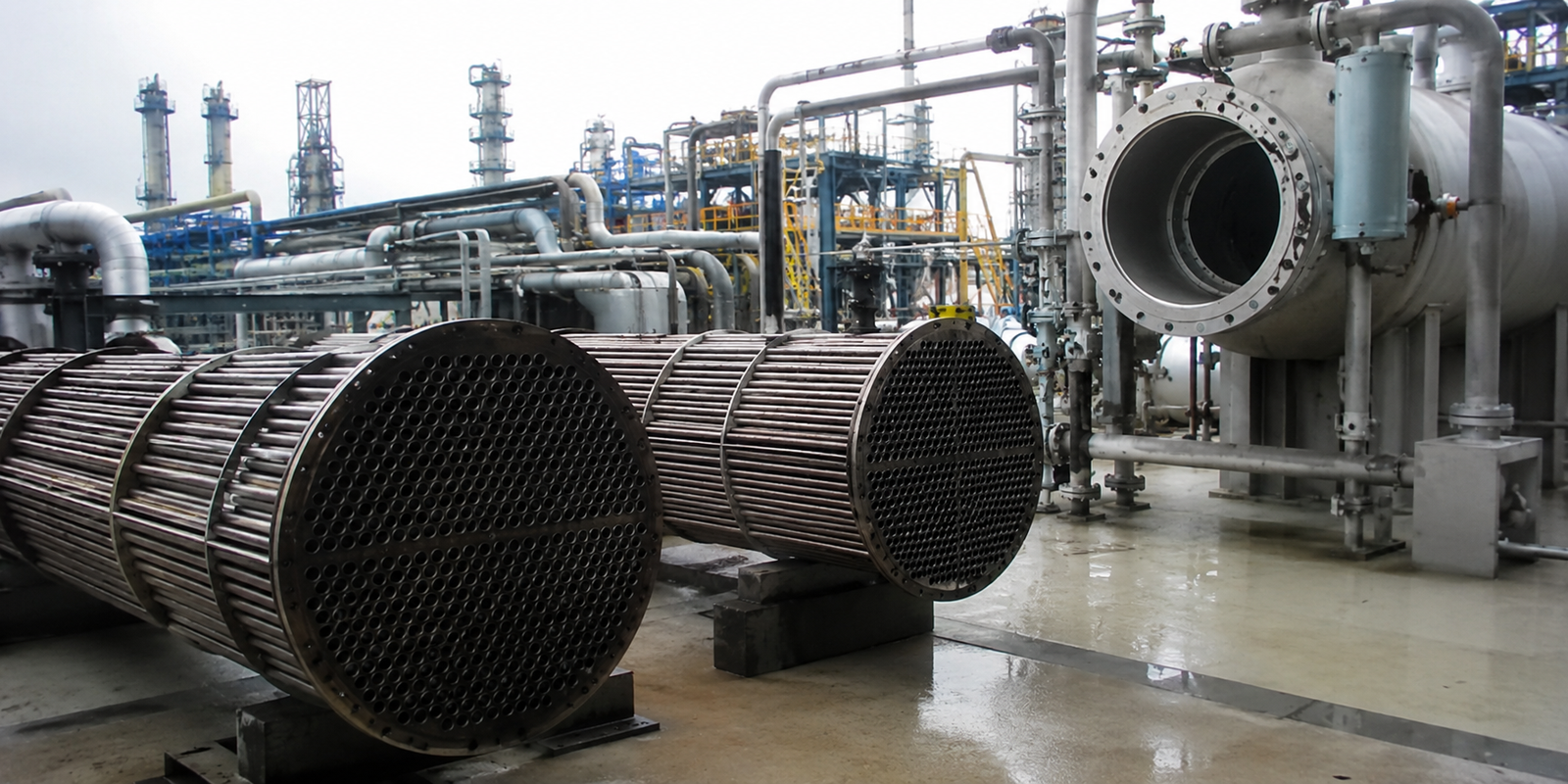
The correct procurement question is therefore not simply:
“Will the tubes be hydrostatically tested?”
A more complete question is:
“Which product and equipment tests apply, what does each test demonstrate, how will it be performed safely, and which records will confirm that the specified coverage and acceptance criteria were achieved?”
This guide explains how buyers can answer those questions without over-testing, under-testing, or confusing material-standard compliance with final equipment pressure integrity.
First Distinguish the Four Testing Stages
One of the most common specification errors is to use the term “tube pressure test” for several different activities.
| Testing Stage | Typical Test Object | Primary Purpose | Typical Responsible Party |
|---|---|---|---|
| Raw or intermediate material testing | Billet, strip or tube hollow | Verify raw-material or process requirements | Raw-material mill |
| Finished tube product testing | Individual straight tube or production lot | Verify compliance with the tube product standard | Tube manufacturer |
| Post-forming or post-fabrication testing | U-bend tube, welded tube assembly or formed component | Check whether later manufacturing introduced damage | Tube fabricator or exchanger manufacturer |
| Completed exchanger testing | Shell side, tube side or complete pressure boundary | Verify assembled equipment pressure integrity and leakage | Heat exchanger manufacturer |
These stages should not be treated as interchangeable.
For example:
- A straight tube can pass its mill hydrostatic test and later be damaged during U bending.
- A completed exchanger can pass a shell-side hydrostatic test even though the original tube certificate is incomplete.
- A tube may pass an individual pressure test but still contain a non-through-wall discontinuity detectable by ultrasonic or eddy-current examination.
- A tube-to-tubesheet joint may leak even when every individual tube passed its mill test.
A complete inspection plan should therefore define the required verification at each relevant stage.
Product Testing and Equipment Testing Follow Different Requirements
Finished tube product test
A product-standard test is used to verify that the delivered tube complies with its material specification.
Depending on the product standard and tube construction, the required verification may include:
- Hydrostatic testing
- Pneumatic testing
- Electromagnetic testing
- Eddy-current testing
- Ultrasonic testing
- Flattening or reverse-flattening testing
- Flaring or expansion testing
- Dimensional inspection
- Surface examination
Completed heat exchanger test
The exchanger test evaluates an assembled pressure boundary that may include:
- Tubes
- Tubesheets
- Tube-to-tubesheet joints
- Shell
- Channel
- Bonnet
- Covers
- Nozzles
- Flanges
- Gaskets
- Welded joints
The pressure is normally established from the applicable design code, maximum allowable working pressure, test-temperature allowable stresses, equipment configuration, and approved calculation.
| Topic | Tube Product Test | Completed Exchanger Test |
|---|---|---|
| Governing basis | ASTM, ASME material specification or purchase order | Pressure-vessel code, TEMA and project specification |
| Test object | Individual tube or tube lot | Assembled shell-side or tube-side boundary |
| Pressure calculation | Product-standard formula or specified value | Design-code calculation |
| Test purpose | Product integrity and standard compliance | Pressure-boundary integrity and leakage |
| Tube-to-tubesheet joint included | Normally no | Yes |
| Flanges and gaskets included | No | Usually yes |
| Differential pressure across tube wall | Individual internal test condition | Depends on which exchanger side is pressurized |
| Authorized inspector involvement | Project-dependent | May be required by code and jurisdiction |
| Final record | Tube test certificate or report | Equipment pressure-test report and code documentation |
A purchase order should specify both requirements when both are applicable.
Pressure Test Parameters Are Context-Dependent—but Not Arbitrary
The parameters are influenced by the application, but they cannot be selected only from experience or preference.
They must be derived from a defined hierarchy.
Recommended hierarchy
- Applicable law or jurisdictional regulation
- Pressure-equipment design code
- Tube product standard
- Purchaser's technical specification
- Approved drawing and data sheet
- Inspection and Test Plan
- Qualified pressure-test procedure
- Supplier's internal work instruction
If two documents conflict, the purchase contract should establish which requirement takes precedence.
Parameters that require confirmation
| Parameter | Questions to Resolve |
|---|---|
| Test object | Individual tube, U-bend, tube bundle, shell side or tube side? |
| Test purpose | Proof, gross leakage, sensitive leakage or product-standard compliance? |
| Test pressure | Which formula, reference pressure and stress ratio apply? |
| Test medium | Water, another liquid, air, nitrogen, helium or another approved medium? |
| Test temperature | What minimum and maximum test-metal temperature apply? |
| Holding period | How long after stabilization must the test pressure be maintained? |
| Pressure increase | Is staged pressurization required? |
| Pressure decrease | How will the system be depressurized safely? |
| Inspection pressure | Is examination performed at full pressure or a reduced pressure? |
| Coverage | Which tubes, surfaces, welds and joints are included? |
| Acceptance | No visible leakage, no pressure loss, specified leak rate or another criterion? |
| Instrumentation | Gauge range, accuracy, calibration and location? |
| Static head | Is correction required for vertical height differences? |
| Cleaning | What medium quality and cleanliness are required? |
| Drying | How will residual liquid be removed? |
| Documentation | Which data and signatures must appear in the report? |
A specification that provides only the test pressure leaves many important variables undefined.
Why “1.5 Times Design Pressure” Is Not a Universal Rule
The statement that heat exchanger tubes are normally tested at 1.5 times design pressure is too broad.
Different standards use different methods.
For completed pressure vessels under ASME Section VIII, Division 1 pressure-testing rules, hydrostatic and pneumatic tests use different minimum factors and may include an allowable-stress ratio between test and design temperatures.
The commonly discussed ASME Section VIII, Division 1 bases include:
- A hydrostatic test basis associated with 1.3
- A pneumatic test basis associated with 1.1
The complete code calculation, current edition, stress ratio, static head, component limits, and approved procedure must still be checked.
Other standards may use:
- A pressure based on design pressure
- A pressure based on MAWP
- A product-standard tube formula
- A maximum allowable fiber stress
- A fixed maximum test pressure
- A purchaser-specified pressure
- An alternative NDT method instead of hydrostatic testing
- A combination of pressure testing and NDT
Common specification errors
| Incorrect Approach | Why It Is Unsafe or Incomplete |
|---|---|
| Apply 1.5 × design pressure to every tube | Ignores governing standard and actual tube dimensions |
| Use exchanger test pressure for individual tubes | Product test and equipment test serve different purposes |
| Use operating pressure instead of design or MAWP basis | May conflict with the code calculation |
| Ignore test-temperature stress ratio | Material allowable stress may differ at design and test temperatures |
| Ignore static liquid head | Lower parts of a vertical system may experience higher pressure |
| Round pressure upward without review | May exceed the permitted stress or weakest component rating |
| Reduce pressure because the tube is thin | May violate the product standard |
| Increase pressure “for extra safety” | Over-testing can deform or damage compliant components |
Higher pressure does not automatically provide better quality assurance.
The correct pressure is the pressure required by the applicable standard and approved engineering basis.
Understand the Purpose: Proof Test, Pressure Test, or Leak Test
These terms are sometimes used interchangeably, but they may describe different objectives.
| Test Purpose | Main Question | Typical Acceptance Focus |
|---|---|---|
| Proof or strength test | Can the component sustain the specified test load without unacceptable deformation or failure? | Structural response and absence of failure |
| Hydrostatic pressure test | Can the liquid-filled pressure boundary sustain the required pressure? | Leakage, pressure integrity and deformation |
| Pneumatic pressure test | Can the gas-pressurized boundary sustain the required pressure? | Integrity and leakage under controlled conditions |
| Gross leak test | Is there a visible or readily detectable leak? | Bubbles, pressure loss or visible fluid |
| Sensitive leak test | Is leakage below a specified low leak-rate threshold? | Quantified leak rate |
| Product-standard test | Does the tube meet the test requirements of its product specification? | Standard-specific acceptance |
| Service leak test | Does the assembled system retain the intended service or surrogate fluid? | Project-defined leakage criterion |
A hydrostatic test may demonstrate pressure integrity but may not be sensitive enough for extremely small leak-rate requirements.
A sensitive helium or tracer-gas test may detect very small leakage but does not automatically replace the required proof pressure test.
The test purpose should be stated before the method is selected.
Hydrostatic and Pneumatic Testing Are Not Equivalent
Hydrostatic testing
Hydrostatic testing normally uses water or another approved incompressible liquid.
Possible advantages include:
- Lower stored energy than a comparable gas test
- Visible leakage
- Broad industry familiarity
- Ability to apply proof pressure to the full boundary
Possible concerns include:
- Residual water
- Internal contamination
- Freezing
- Disposal requirements
- Drying difficulty
- Material or service incompatibility
- Large test weight
- Support loading
- Static-head differences
Pneumatic testing
Pneumatic testing normally uses air, nitrogen, or another approved gas.
Possible reasons for its use include:
- Liquid contamination is unacceptable
- Complete drying cannot be assured
- The component cannot safely support the liquid weight
- The applicable standard requires or permits it
- A gas-based leak test is needed
However, compressed gas stores substantially more energy than an incompressible liquid.
This creates greater consequences if a rupture occurs.
| Topic | Hydrostatic Test | Pneumatic Test |
|---|---|---|
| Stored energy | Lower | Higher |
| Typical test factor | Code-dependent | Often lower than hydrostatic under the same code |
| Leak visibility | Often visible | May require soap solution, pressure monitoring or instrumentation |
| Residual medium | Liquid may remain | Gas is easier to remove |
| Test weight | Can be significant | Lower |
| Drying requirement | Often important | Usually less demanding |
| Rupture hazard | Serious | Potentially more severe |
| Exclusion zone | Required as appropriate | Generally requires stricter control |
| Medium compatibility | Must be checked | Must be checked |
| Safety procedure | Required | Especially critical |
A pneumatic test should not be selected simply because it is faster or easier.
Test Medium Selection Must Be Technically Defined
“Use clean water” is not a complete requirement.
The purchaser may need to define:
- Water source
- Chloride limit
- Conductivity
- pH
- Hardness
- Suspended solids
- Microbiological condition
- Oil content
- Chemical additives
- Corrosion inhibitor
- Temperature
- Filtration
- Reuse policy
- Disposal
- Flushing
- Drying acceptance
Medium-selection questions
| Material or Service Concern | Question to Confirm |
|---|---|
| Titanium tubing | Are foreign-metal contamination and surface cleanliness controlled? |
| Nickel-alloy tubing | Is the medium compatible with the alloy and final service? |
| Stainless steel components in the exchanger | Is chloride content limited by the project specification? |
| Oxygen or high-purity service | Are hydrocarbons, particles and cleaning residues controlled? |
| Pharmaceutical or semiconductor service | Does the water meet the required purity level? |
| Freezing environment | Can all liquid be removed before exposure to low temperature? |
| Long storage after test | Is drying or preservation required? |
| Carbon-steel shell with alloy tubes | Is temporary corrosion protection necessary? |
| Internally coated equipment | Is the test medium compatible with the coating? |
| Dissimilar metals | Can stagnant residual water create galvanic or crevice conditions? |
ASTM B600-22 provides guidance on removing contaminants from titanium and titanium-alloy surfaces. It does not prescribe a universal hydrotest-water specification, but it supports controlling shop soils, foreign substances, oxides, and cleaning processes where these can affect final product quality.
Do not make unsupported material assumptions
It is inaccurate to state that titanium heat-exchanger tubes generally require pneumatic testing because ordinary water will cause chloride stress-corrosion cracking.
The appropriate approach is to:
- Review all wetted materials.
- Apply the project water-quality specification.
- Prevent foreign contamination.
- Drain the component fully.
- Flush when required.
- Dry to the specified acceptance level.
- Record the process.
Test Temperature Requires More Than Recording Room Temperature
Test temperature can affect:
- Material strength
- Allowable-stress ratio
- Fracture resistance
- Seal behaviour
- Fluid viscosity
- Instrument readings
- Pressure stability
- Risk of freezing
- Thermal expansion
A pressure test is generally not intended to simulate the exchanger's full operating temperature unless a specific approved procedure requires such testing.
Why elevated-temperature simulation is usually inappropriate as a default
- The applicable design code normally defines a test-temperature basis.
- The completed exchanger may contain multiple materials with different limits.
- Gaskets and temporary closures may not be designed for elevated-temperature testing.
- Heating can create additional stored energy and safety risk.
- Temperature gradients can distort pressure readings.
- A static pressure test does not reproduce service creep or thermal fatigue.
Test-temperature checklist
- [ ] Minimum permitted metal temperature confirmed
- [ ] Maximum permitted test temperature confirmed
- [ ] Test-medium temperature recorded
- [ ] Component temperature stabilized
- [ ] Ambient temperature recorded where required
- [ ] Freezing risk addressed
- [ ] Allowable-stress ratio calculated where applicable
- [ ] Temporary seals compatible with test temperature
- [ ] Temperature instruments calibrated
- [ ] Temperature change during hold period monitored
For a completed exchanger, the lowest-temperature-sensitive component may govern the test procedure rather than the alloy tubes alone.
Holding Time Is Not Universally 30 Minutes
The required holding period can vary by:
- Governing code
- Product standard
- Component size
- Test purpose
- Pressure stabilization
- Temperature stabilization
- Inspection access
- Leak-detection method
- Purchaser specification
- Authorized Inspector requirements
A valid procedure should distinguish between:
- Time required to reach test pressure
- Time required for temperature and pressure stabilization
- Time maintained at test pressure
- Time used for visual examination
- Time used for sensitive leak detection
- Depressurization time
Why a fixed arbitrary hold time can be misleading
| Situation | Problem With an Arbitrary Time |
|---|---|
| Very small individual tube | Thirty minutes may add no useful verification |
| Large exchanger | Thirty minutes may be insufficient for complete inspection |
| Temperature still changing | Pressure variation may be mistaken for leakage |
| Sensitive leak test | Stabilization and background measurement may require another method |
| Pneumatic test | Excessive exposure at full stored energy may increase risk |
| Product standard specifies another duration | Purchase order may conflict with the standard |
The hold time should be stated together with its purpose and the point at which timing begins.
Pressure Increase and Release Should Be Controlled
A pressure-test procedure should describe how pressure is applied and removed.
Staged pressurization may include
- Initial low-pressure leak check
- Intermediate pressure hold
- Final approach to test pressure
- Stabilization
- Inspection
- Controlled reduction to examination pressure where applicable
- Final depressurization
- Drainage or venting
Risks of uncontrolled pressurization
- Hydraulic shock
- Gauge overshoot
- Local deformation
- Temporary-closure failure
- Trapped air during hydrostatic testing
- Unstable gas compression
- Incomplete venting
- Misinterpretation of transient pressure loss
Required controls may include
- Calibrated relief device
- Controlled pump or regulator
- Independent pressure indication
- Remote operation
- Isolation valves
- Check valves
- Vent points
- Drain points
- Exclusion zone
- Emergency depressurization plan
The test should never depend solely on an operator stopping a pump at the exact required pressure without overpressure protection.
Remove Trapped Air During Hydrostatic Testing
Air trapped within a liquid-filled test system increases stored energy and can make the test more hazardous.
It can also interfere with pressure stability.
Common air-trap locations
- U-bend apex
- High nozzles
- Channel partitions
- Dead legs
- Instrument connections
- Tube bundle high points
- Floating-head regions
- Temporary blind arrangements
The hydrostatic procedure should identify:
- Fill point
- Vent points
- Drain points
- Equipment orientation
- Air-removal confirmation
- Temporary piping arrangement
A system is not fully hydrostatically filled merely because liquid appears at one vent.
Account for Static-Head Pressure
In a tall or vertically oriented test object, the pressure at the lowest point can be higher than the gauge pressure at an elevated measurement point because of the liquid column.
This is called static or hydrostatic head.
Why it matters
- The bottom of the component may experience pressure above the nominal test value.
- A gauge at the pump may not show the pressure at the lowest point.
- A gauge at the bottom may read higher than a gauge near the top.
- The code test pressure may need to be evaluated at a defined reference point.
Information to record
| Item | Required Detail |
|---|---|
| Gauge elevation | Relative to the test object |
| Highest and lowest points | Vertical distance |
| Test-medium density | At the test temperature |
| Reference test point | Defined by procedure |
| Static-head correction | Calculation or confirmation |
| Maximum local pressure | Checked against component limits |
Static head may be negligible for a short individual tube but important for a large vertical exchanger.
Pressure Instruments Must Be Suitable and Calibrated
A test report stating only “pressure passed” does not demonstrate that the pressure was measured reliably.
Instrument requirements to define
- Instrument type
- Measurement range
- Accuracy class
- Resolution
- Calibration date
- Calibration certificate
- Calibration traceability
- Installation location
- Number of gauges
- Environmental suitability
- Data-logging interval
- Independent verification
Gauge-range considerations
A gauge with an excessively high full-scale range may not provide enough resolution near the test pressure.
A gauge with too low a range may be damaged by pressure overshoot.
The governing procedure or code may specify acceptable relationships between test pressure and gauge range.
Recommended report fields
| Field | Example of Required Information |
|---|---|
| Gauge identification | Serial or asset number |
| Range | Minimum and maximum pressure |
| Accuracy | Manufacturer or calibration value |
| Calibration due date | Valid during test |
| Location | Pump discharge, test object or remote point |
| Reading method | Analogue, digital or data logger |
| Secondary gauge | Identification and location |
| Temperature instrument | ID and calibration |
| Relief device | Set pressure and certificate |
Calibration records should be linked to the pressure-test report.
Acceptance Criteria Must Be Written Before Testing
“Pass the pressure test” is not a complete acceptance criterion.
Possible criteria include:
- No visible leakage
- No pressure-boundary rupture
- No unacceptable permanent deformation
- No leakage from tube-to-tubesheet joints
- No pressure loss beyond an allowed amount after temperature correction
- Leak rate below a specified value
- No sweating or weeping
- No leakage from temporary closures
- No abnormal noise or movement
- No new relevant indications during post-test NDT
Sources of pressure reduction that are not necessarily leaks
- Cooling of the test medium
- Expansion of the component
- Compression or dissolution of trapped gas
- Hose expansion
- Pump-valve leakage
- Gauge drift
- Seal relaxation
- Movement of temporary closures
A pressure drop should be investigated, but it should not automatically be classified as a tube leak without confirming temperature and system effects.
A Pressure Test Does Not Detect Every Tube Defect
Pressure testing is important, but its limitations must be understood.
Defects that may not cause leakage during a single test
- Non-through-wall crack
- Shallow surface crack
- Lamination
- Local wall thinning
- Small inclusion
- Incomplete weld penetration that remains non-leaking
- Discontinuity oriented unfavourably to the applied stress
- Defect that opens only during thermal cycling
- Defect masked by temporary debris
- Small leak below the observation sensitivity
ASME BPVC Section V includes methods such as ultrasonic, eddy-current, visual, penetrant, radiographic, and leak testing because different methods respond to different defect types.
Pressure testing and NDT are complementary
| Method | Main Strength | Main Limitation |
|---|---|---|
| Hydrostatic testing | Demonstrates liquid-pressure integrity | Limited sensitivity to non-through-wall defects |
| Pneumatic testing | Pressure integrity without residual liquid | Higher stored-energy risk |
| Eddy-current testing | Sensitive to surface and near-surface discontinuities in conductive tubes | Calibration and geometry affect response |
| Ultrasonic testing | Wall measurement and internal-discontinuity detection | Coupling and curvature must be controlled |
| Visual inspection | Surface and workmanship review | Cannot detect hidden defects |
| Dye penetrant testing | Surface-breaking discontinuities | Requires clean accessible surface |
| Helium leak testing | High sensitivity to leakage | Does not prove full structural capacity |
| Dimensional inspection | Verifies wall, OD, ovality and length | Does not directly prove material soundness |
A buyer should not delete a required NDT method merely because hydrostatic testing is performed.
Likewise, an NDT method should not replace a mandatory pressure test unless the applicable standard expressly permits the substitution.
Tube Construction Can Change the Required Tests
The test plan may differ for:
- Seamless tubes
- Welded tubes
- Welded and cold-worked tubes
- Internally or externally enhanced tubes
- U-bend tubes
- Finned tubes
- Small-diameter light-wall tubes
ASTM B338, for example, distinguishes between seamless, welded, and welded/cold-worked titanium heat-exchanger tubing.
The cited requirements include different combinations of:
- Electromagnetic testing
- Ultrasonic testing
- Hydrostatic testing
- Pneumatic testing
- Flattening testing
- Reverse-flattening testing
This demonstrates why a purchase order should not state only:
“Titanium tubes, 100% pressure tested.”
It should identify:
- ASTM grade
- Product form
- Current or contractually specified edition
- Required NDT methods
- Required pressure test
- Permitted alternatives
- Supplementary requirements
- Reporting requirements
Nickel-Alloy Standards Must Also Be Checked Individually
ASTM B163 covers specific seamless nickel and nickel-alloy condenser and heat-exchanger tubes.
Other nickel-alloy products may fall under different standards, such as:
- ASTM B167
- ASTM B423
- ASTM B444
- ASTM B622
- ASTM B704
- Other alloy-specific product standards
ASTM B829-24 provides general requirements for several seamless nickel and nickel-alloy pipe and tube standards.
ASTM states that:
- The product specification takes precedence in a conflict.
- Some general test requirements apply only when required by the product standard or purchase order.
Buyer checklist for nickel-alloy tubes
- [ ] Correct alloy and UNS number
- [ ] Correct tube product standard
- [ ] Seamless or welded product form
- [ ] Current or agreed standard edition
- [ ] Applicable general-requirements standard
- [ ] Hydrostatic test requirement
- [ ] Nondestructive electric test requirement
- [ ] Permitted substitution between tests
- [ ] Maximum test pressure where applicable
- [ ] Mechanical-property condition
- [ ] Minimum-wall or average-wall basis
- [ ] Supplementary purchaser requirements
The alloy name alone does not define the pressure-test requirement.
Internal Pressure Testing Does Not Prove External-Pressure Resistance
An individual tube hydrostatic test normally applies internal pressure.
This creates primarily tensile circumferential stress in the tube wall.
External pressure or vacuum can create a different failure mode involving:
- Ovalization
- Elastic instability
- Plastic collapse
- Local buckling
- Support-spacing effects
- Initial geometric imperfections
A successful internal hydrostatic test therefore does not automatically verify resistance to:
- Shell-side pressure with low tube-side pressure
- Full tube-side vacuum
- Steam collapse conditions
- Differential-pressure transients
- Unsupported-span instability
Internal and external pressure comparison
| Condition | Dominant Concern |
|---|---|
| Tube internal pressure above shell pressure | Tensile wall stress |
| Shell pressure above tube pressure | External-pressure collapse |
| Tube-side vacuum with shell pressure | Differential external pressure |
| Both sides pressurized equally | Lower differential tube-wall pressure |
| Rapid depressurization on one side | Transient differential pressure |
| Blocked-in liquid heated after testing | Thermal overpressure |
External-pressure capability should be addressed through the mechanical design calculation and applicable code, not inferred from an internal pressure-test certificate.
The Completed Exchanger Test Can Load the Tubes Differently
During final exchanger testing, the shell side and tube side may be tested separately.
This can expose the tube wall and tube-to-tubesheet joint to differential pressures that differ from normal operation.
Questions to confirm
| Test Question | Why It Matters |
|---|---|
| Which side is tested first? | Test sequence may affect access and leak identification |
| Is the opposite side open, vented or pressurized? | Determines differential pressure |
| What pressure acts across the tube wall? | May govern collapse or tensile stress |
| Are the tube ends visible? | Needed for joint leakage examination |
| Are temporary covers used? | They must withstand the test load |
| Is shell-side water trapped after the test? | Affects drainage and drying |
| Can the floating head move? | Temporary restraint may be required |
| Are expansion joints locked or free? | Test configuration affects load |
| Is the bundle supported for water-filled weight? | Test weight may exceed operating weight |
| Are tube-to-tubesheet joints seal or strength welded? | Acceptance and inspection may differ |
The exchanger test procedure should be reviewed against the mechanical design and assembly configuration.
Test Sequence Can Affect Leak Identification
A common test sequence may involve separate shell-side and tube-side tests, but the exact arrangement depends on exchanger type.
Possible configurations include:
- Fixed tubesheet exchanger
- U-tube exchanger
- Floating-head exchanger
- Kettle reboiler
- Double-tubesheet exchanger
- High-pressure feedwater heater
- Clad tubesheet exchanger
Leak-source identification
A detected pressure loss may originate from:
- Tube body
- Tube-to-tubesheet joint
- Channel gasket
- Floating-head gasket
- Nozzle weld
- Tubesheet weld
- Temporary blind
- Test hose
- Instrument connection
- Pump isolation valve
The procedure should provide a method to distinguish a tube leak from a temporary test-system leak.
Straight-Tube Testing Does Not Verify Damage Created Later
Heat-exchanger tubes may undergo additional operations after the mill test:
- Cutting
- Straightening
- U bending
- Tube-end forming
- Mechanical expansion
- Hydraulic expansion
- Welding
- Heat treatment
- Cleaning
- Grinding
- Marking
- Transportation
Each operation can introduce new conditions.
| Fabrication Operation | Possible New Risk |
|---|---|
| U bending | Wall thinning, ovality, wrinkles or surface cracking |
| Tube expansion | Work hardening, thinning or transition-zone damage |
| Tube-to-tubesheet welding | Weld defects, contamination or residual stress |
| Heat treatment | Surface oxide, dimensional change or altered condition |
| Grinding | Local wall reduction |
| Cleaning | Chemical attack or residue |
| Handling | Dents and scratches |
| Marking | Surface indentation or contamination |
The purchaser should decide whether the final inspection plan requires:
- Post-bend visual inspection
- Post-bend dimensional inspection
- Bend-area UT
- Bend-area eddy-current testing
- Post-weld leak testing
- Completed exchanger pressure testing
- Final baseline eddy-current examination
A mill certificate cannot verify workmanship performed after shipment from the tube mill.
Static Pressure Testing Cannot Prove Long-Term Service Life
A successful test confirms performance under the test conditions at that time.
It does not prove unlimited resistance to every service damage mechanism.
A static test does not by itself establish
- Fatigue life
- Creep life
- Thermal-fatigue resistance
- Corrosion rate
- Pitting resistance
- Crevice-corrosion resistance
- Stress-corrosion-cracking resistance
- Hydrogen damage resistance
- Erosion-corrosion life
- Flow-induced vibration resistance
- Fretting resistance
- Fouling behaviour
- Long-term gasket relaxation
- Tube-support wear
| Long-Term Risk | Appropriate Evaluation |
|---|---|
| Pressure fatigue | Cyclic design analysis or fatigue testing |
| Thermal fatigue | Transient thermal analysis |
| Creep | Elevated-temperature allowable-stress and creep assessment |
| Corrosion | Environment-specific material selection and corrosion data |
| SCC | Material, stress and environment assessment |
| Vibration | Thermal-hydraulic and mechanical vibration analysis |
| Erosion | Velocity, solids and geometry assessment |
| Fouling | Process and cleaning analysis |
Pressure testing is one verification step within a broader design and quality system.
Pressure Testing Does Not Correct an Incorrect Material Selection
A tube made from the wrong alloy can pass a pressure test.
For example, a material may have adequate short-term strength at room temperature while being unsuitable for:
- Hot chlorides
- Reducing acids
- H₂S service
- High-temperature oxidation
- Hydrogen charging
- Crevice-corrosion conditions
- Chemical cleaning
A passed pressure test therefore confirms neither:
- Corrosion suitability
- Correct alloy identity
- Correct heat treatment
- Correct product standard
- Correct long-term service capability
These require separate verification through:
- Material certificate review
- PMI where specified
- Mechanical-property review
- Corrosion assessment
- Heat-treatment records
- Applicable service standards
- Supplier traceability
Supplier Expertise Is Useful—but Does Not Replace Design Authority
A knowledgeable tube supplier can help identify:
- Incorrect product-standard references
- Test methods unavailable for a particular size
- Conflicting hydrostatic and NDT requirements
- Unrealistic test pressures
- Incompatible test media
- Insufficient drying requirements
- Missing document requirements
- Excessive or redundant testing
- Lead-time effects
- Subcontracted test limitations
However, the supplier should not independently alter the test requirement.
Recommended responsibility division
| Party | Primary Responsibility |
|---|---|
| Process engineer | Defines fluids and operating conditions |
| Mechanical designer | Establishes code design and equipment test basis |
| Materials engineer | Confirms alloy and test-medium compatibility |
| Purchaser | Issues complete contractual requirements |
| Tube manufacturer | Applies the correct product standard and reports results |
| Exchanger manufacturer | Develops and performs final equipment test procedure |
| QA/QC team | Reviews records, calibration and acceptance |
| Authorized Inspector | Performs code-defined inspection responsibilities |
| Third-party inspector | Witnesses or reviews agreed activities |
| Supplier | Identifies conflicts and requests clarification |
The supplier's role is to raise technical questions early, not to replace purchaser approval.
What the Supplier Should Clarify Before Quoting
| Clarification Item | Required Information |
|---|---|
| Product | Straight tube, U-bend tube or fabricated assembly |
| Alloy | Grade and UNS number |
| Standard | ASTM, ASME or EN designation and edition |
| Construction | Seamless, welded or welded/cold worked |
| Dimensions | OD, wall basis, length and quantity |
| Test stage | Before forming, after forming or completed exchanger |
| Test method | Hydrostatic, pneumatic, NDT or combination |
| Test pressure | Exact value or governing formula |
| Test medium | Composition and cleanliness requirements |
| Test temperature | Permitted range |
| Hold time | Timing and stabilization definition |
| Coverage | Every tube or sampling plan |
| Acceptance | Leakage, pressure loss and deformation criteria |
| Instrumentation | Accuracy, range and calibration |
| Witnessing | Purchaser, third party or Authorized Inspector |
| Documentation | Report format and certificate type |
| Drying | Method and acceptance requirement |
| Packaging | Protection after testing |
If these details are missing, the supplier should request clarification rather than assuming a standard practice.
Pressure-Test Documentation Should Be Traceable
The final report should identify exactly what was tested.
Recommended pressure-test report fields
| Report Section | Information |
|---|---|
| Project | Customer, PO, item and project number |
| Product | Tube grade, standard, OD, wall and length |
| Identification | Heat number, lot number and bundle number |
| Quantity | Number of tubes tested |
| Coverage | 100% or stated sampling basis |
| Test stage | Straight tube, U-bend or completed exchanger |
| Procedure | Procedure number and revision |
| Governing document | Standard and edition |
| Test method | Hydrostatic or pneumatic |
| Medium | Water, nitrogen or other medium |
| Medium quality | Chloride, conductivity or other specified data |
| Test pressure | Required and actual values |
| Pressure reference | Gauge location and static-head basis |
| Test temperature | Medium and component temperature |
| Stabilization | Time or confirmation |
| Hold period | Start and finish time |
| Pressure instruments | IDs, ranges and calibration dates |
| Temperature instruments | IDs and calibration dates |
| Relief device | Set pressure and identification |
| Acceptance | Defined criteria and result |
| Leakage | Location and disposition if found |
| Repair | Repair and retest information |
| Witness | Operator, inspector and third-party signatures |
| Date | Test date and report issue date |
A statement such as “Hydro test: OK” is not sufficient for a critical project unless the contract permits that level of reporting.
Build the Test Into the Inspection and Test Plan
An Inspection and Test Plan should identify each stage, responsibility and intervention point.
| Activity | Record | Typical Purchaser Status |
|---|---|---|
| Material receipt | MTC and identification review | Review |
| Tube dimensional inspection | Dimensional report | Review or witness |
| Tube NDT | ET/UT report | Review or witness |
| Product pressure test | Tube pressure-test report | Witness or review |
| U bending | Process and dimensional record | Surveillance |
| Post-bend inspection | Visual, UT or ET report | Review |
| Tube-to-tubesheet joining | Procedure and production record | Surveillance |
| Final exchanger hydrotest | Equipment pressure-test report | Hold or witness |
| Pneumatic test | Approved safety procedure | Hold |
| Leak test | Leak-test report | Witness or review |
| Drying and preservation | Cleanliness/drying record | Review |
| Final dossier | Document index | Hold before release |
The terms Hold, Witness, Review, and Surveillance should be defined contractually.
Common Pressure-Test Nonconformities
| Nonconformity | Why It Matters | Recommended Action |
|---|---|---|
| Wrong test pressure used | Test may be invalid or damaging | Stop, verify calculation and assess retest |
| Pressure overshoot | Component may have exceeded permitted stress | Record peak pressure and perform engineering review |
| Gauge calibration expired | Measurement validity is uncertain | Replace gauge and evaluate need for retest |
| Gauge range unsuitable | Required pressure may not be read accurately | Repeat with suitable instrument |
| Test medium not approved | Contamination or compatibility concern | Quarantine, clean and assess |
| Temperature not recorded | Stress ratio or pressure stability cannot be confirmed | Review procedure and consider retest |
| Hold time started before stabilization | Effective examination time may be insufficient | Repeat required hold period |
| Air trapped during hydrotest | Increased stored energy and unstable readings | Depressurize, vent and repeat safely |
| Visible leakage at temporary connection | Product result cannot be confirmed | Repair test setup and repeat |
| Pressure drop without temperature data | Leak cannot be distinguished from cooling | Stabilize and retest |
| Tube leaks after U bending | Straight-tube test did not cover bend damage | Identify cause and revise bending inspection |
| Test report lacks heat numbers | Traceability is incomplete | Reconstruct records or reject documentation |
| Tube quantity not stated | Coverage cannot be verified | Obtain corrected report |
| Unauthorized NDT substituted for hydrotest | Product standard may not permit substitution | Review standard and retest if required |
| Pneumatic test performed without approved safety plan | Personnel risk | Stop work and implement controlled procedure |
| Residual water remains | Corrosion, contamination or freezing risk | Drain, flush, dry and document |
Repeated nonconformities should trigger root-cause analysis rather than repeated retesting alone.
Over-Testing Can Also Create Risk
More testing is not always better.
Possible consequences of unnecessary or incorrectly specified testing include:
- Plastic deformation
- Damage to temporary closures
- Unnecessary stored-energy exposure
- Surface contamination
- Residual moisture
- Delayed delivery
- Duplicate inspection cost
- Additional handling damage
- Conflict between standards
- False confidence from an unsuitable test
Examples
| Over-Testing Request | Better Approach |
|---|---|
| Apply exchanger hydrotest pressure to every loose tube | Use the applicable tube product-standard requirement |
| Require hydro, pneumatic, ET and UT without technical basis | Select the combination required by the standard and risk |
| Require repeated hydrotests after every handling stage | Identify stages capable of creating relevant damage |
| Increase pressure above code minimum “for safety” | Obtain engineering approval and stress evaluation |
| Require long hold time for very small tubes | Follow the relevant product standard |
| Use ultra-pure water without a service need | Define cleanliness proportionate to risk |
| Require helium testing without a leak-rate criterion | State sensitivity and acceptance requirement |
The objective is a technically justified test plan, not the largest possible number of tests.
Risk-Based Test Planning
A risk-based review can help determine whether project requirements should exceed the base product standard.
| Risk Factor | Possible Additional Control |
|---|---|
| Toxic process fluid | More sensitive final leak testing |
| Flammable fluid | Enhanced joint inspection and leak acceptance |
| Cross-contamination risk | Double-tubesheet design or sensitive leak test |
| High differential pressure | Detailed tube-wall and joint assessment |
| Thin-wall tubing | Tighter dimensional and NDT controls |
| U-bend tube | Post-bend inspection |
| Welded tube | Weld-seam NDT and form-specific tests |
| Critical shutdown consequence | Increased witnessing and documentation |
| High-purity service | Controlled medium, cleaning and drying |
| Long inaccessible service | Baseline ET or UT records |
| Cyclic service | Fatigue assessment rather than higher static test alone |
| Corrosive environment | Materials evaluation rather than higher test pressure |
| External-pressure case | Collapse design and geometric control |
Additional controls should address the actual failure mechanism.
What Buyers Should Include in the RFQ
| RFQ Category | Required Information |
|---|---|
| Application | Heat exchanger service and equipment type |
| Design code | ASME, EN, PED, TEMA or project basis |
| Tube alloy | Grade and UNS number |
| Product standard | ASTM, ASME or EN designation and edition |
| Tube form | Seamless, welded or welded/cold worked |
| Dimensions | OD, wall basis, length and quantity |
| Fabrication | Straight, U-bend, expanded or welded |
| Product test | Required pressure or governing product standard |
| Product NDT | ET, UT or other required method |
| Final equipment test | Shell-side and tube-side requirements |
| Test pressure | Formula, MAWP basis or stated value |
| Test medium | Water, nitrogen or other approved medium |
| Medium quality | Chloride, conductivity, pH and cleanliness where required |
| Test temperature | Permitted range |
| Hold time | Required period and stabilization definition |
| Pressure increase | Staged or continuous procedure |
| Acceptance | Leakage, pressure loss and deformation criteria |
| Instrumentation | Accuracy, range and calibration |
| Static head | Reference point and correction |
| Post-test cleaning | Flushing requirements |
| Drying | Method and acceptance |
| Traceability | Heat, lot and individual or bundle identification |
| Reporting | Required fields and certificate format |
| Inspection | Hold, witness and review points |
| Third party | Agency and scope |
| Retest | Permitted retest and repair procedure |
| Packaging | Protection after test and drying |
Supplier Review Checklist
Standards and technical basis
- [ ] Correct tube product standard
- [ ] Correct standard edition
- [ ] General-requirements standard identified
- [ ] Final exchanger design code identified
- [ ] Product and equipment tests separated
- [ ] Test pressure calculation reviewed
- [ ] Permitted NDT substitutions confirmed
- [ ] Acceptance criteria documented
Test equipment
- [ ] Pump or gas-control system suitable
- [ ] Relief device installed
- [ ] Pressure gauges calibrated
- [ ] Gauge range appropriate
- [ ] Temperature instruments calibrated
- [ ] Data logger available where required
- [ ] Test fixture rated for pressure
- [ ] Temporary closures approved
- [ ] Vent and drain system available
Safety
- [ ] Written test procedure
- [ ] Risk assessment
- [ ] Exclusion zone
- [ ] Remote pressurization where required
- [ ] Controlled depressurization
- [ ] Emergency response plan
- [ ] Stored-energy assessment for pneumatic test
- [ ] Personnel training
- [ ] Test-area barriers and signs
Medium and cleanliness
- [ ] Approved test medium
- [ ] Medium-quality report
- [ ] Contamination control
- [ ] Filling and venting procedure
- [ ] Drainage plan
- [ ] Flushing procedure
- [ ] Drying procedure
- [ ] Dryness acceptance
- [ ] Waste-disposal method
Documentation
- [ ] Tube heat and lot traceability
- [ ] Test report sample reviewed
- [ ] Calibration certificates available
- [ ] Procedure revision controlled
- [ ] Operator qualification documented
- [ ] Third-party witness process defined
- [ ] Retest records retained
- [ ] Final dossier index agreed
Incoming Document Review
Before releasing tubes for fabrication, the purchaser should verify the pressure-testing records.
Document checks
- Confirm the supplier and manufacturing site.
- Confirm the PO and item number.
- Confirm alloy and UNS designation.
- Confirm tube product standard.
- Confirm seamless or welded construction.
- Confirm dimensions and wall basis.
- Match heat numbers to the MTC.
- Match heat and lot numbers to tube markings.
- Verify the required test method.
- Verify actual test pressure.
- Verify test medium.
- Verify test date.
- Verify test temperature where required.
- Verify hold period.
- Verify quantity and coverage.
- Verify gauge IDs.
- Verify calibration validity.
- Verify acceptance criteria.
- Verify inspector signatures.
- Review any repair and retest records.
- Confirm required NDT reports are also present.
- Confirm drying or preservation records where required.
A complete report should make it possible to determine exactly which tubes were tested and under which conditions.
Frequently Asked Questions
Are all heat exchanger tubes normally hydrostatically tested?
No. The required method depends on the applicable tube product standard, product form, project specification, and permitted test alternatives. Some standards require hydrostatic testing, some permit pneumatic testing, and some specify NDT or a combination of methods.
Is the standard test pressure always 1.5 times design pressure?
No. Different codes and product standards use different pressure bases and factors. ASME Section VIII, Division 1, for example, uses different bases for hydrostatic and pneumatic testing. The applicable calculation and current code edition must be reviewed.
What is the difference between a tube mill test and the final exchanger hydrotest?
The mill test verifies the individual tube product. The final exchanger test verifies the assembled pressure boundary, including tubesheets, tube joints, welds, flanges, gaskets, shell, and channel components.
Can eddy-current or ultrasonic testing replace hydrostatic testing?
Only when the applicable product standard or approved purchase specification permits that substitution. NDT and hydrostatic testing detect different types of problems and should not be treated as automatically interchangeable.
Does a passed hydrostatic test prove that the tube has no defects?
No. Non-through-wall cracks, laminations, local thinning, and other discontinuities may not leak during a static hydrotest. Suitable NDT may still be required.
Does hydrostatic testing prove resistance to external pressure?
No. An internal pressure test does not prove resistance to external-pressure collapse, vacuum, or shell-to-tube differential pressure. Those conditions require mechanical design evaluation.
Should titanium heat exchanger tubes always be pneumatically tested?
No. The method should follow the applicable standard and project requirements. If liquid testing is used, cleanliness, contamination control, drainage, and drying should be defined.
Is demineralized water always required?
Not for every project. The required water quality depends on the materials, final service, cleanliness requirements, storage period, and purchaser specification. The water-quality limits should be stated rather than assumed.
How long should test pressure be held?
There is no universal holding time for every tube or exchanger. The governing standard and approved procedure should define the holding period, stabilization requirements, and examination time.
Should heat exchanger tubes be pressure tested at operating temperature?
Not normally as a general rule. The applicable product standard or equipment code defines the test-temperature basis. A high-temperature service condition is usually addressed through material properties and design calculations, not by automatically testing at operating temperature.
Why is pneumatic testing more hazardous?
Compressed gas stores more recoverable energy than an incompressible liquid at a comparable pressure. A rupture can therefore release energy more violently, requiring stricter procedural and exclusion-zone controls.
What causes pressure to fall even when no leak is visible?
Possible causes include cooling of the medium, expansion of hoses or components, trapped gas, gauge drift, temporary-valve leakage, or seal relaxation. Temperature and system conditions should be stabilized before concluding that the tube leaks.
Should U-bend tubes be retested after bending?
This depends on the product standard and project specification. Because bending can introduce thinning, ovality, wrinkles, or cracks, post-bend visual, dimensional, UT, ET, or pressure verification may be required for critical applications.
Does a pressure test verify corrosion resistance?
No. It verifies short-term pressure integrity under the test conditions. Corrosion resistance must be established through material selection, service data, corrosion testing, and operating controls.
Who should determine the final pressure test requirement?
The requirement should come from the applicable code, equipment designer, purchaser specification, and product standard. The supplier should review feasibility and identify conflicts but should not change the requirement without approval.
What records should buyers request?
Request the pressure-test procedure, report, actual pressure, medium, temperature, hold period, instrument IDs, calibration records, tube heat and lot numbers, quantity tested, acceptance result, inspector signatures, and any repair or retest records.
Conclusion
Confirming pressure testing requirements for heat exchanger tubes is not a routine administrative step.
It requires a clear distinction between:
- Individual tube product testing
- Post-forming or post-fabrication verification
- Tube-to-tubesheet joint examination
- Completed shell-side and tube-side equipment testing
- Sensitive leak testing
- In-service inspection
A technically complete requirement should define:
- Governing standard and edition
- Test object and fabrication stage
- Test purpose
- Test pressure and calculation basis
- Test medium and cleanliness
- Test temperature
- Holding and stabilization time
- Pressure increase and decrease procedure
- Instrument range, accuracy, and calibration
- Static-head correction
- Inspection coverage
- Acceptance criteria
- NDT requirements
- Drainage, cleaning, and drying
- Safety controls
- Traceability and reporting
The pressure test should be stringent enough to satisfy the product standard, design code, and project risk, but it should not be increased arbitrarily or treated as a substitute for material selection, NDT, fatigue analysis, corrosion assessment, or external-pressure design.
For buyers, the most effective approach is to include the complete testing basis in the RFQ and resolve conflicts before production begins.
For tube and heat exchanger manufacturers, the correct approach is to apply the specified standard, use a controlled and safe procedure, maintain calibrated equipment, preserve heat and lot traceability, and report the actual test conditions rather than providing only a generic pass statement.
Clear agreement before manufacturing helps prevent invalid tests, unnecessary retesting, contaminated tubes, incomplete documentation, delayed equipment release, and misunderstandings over whether the tube product or the completed exchanger has actually been verified.