
How Should Buyers Select Nickel Alloy Capillary Tubes for Industrial Applications?
Nickel alloy capillary tubes are used when a project requires a combination of small internal diameter, controlled flow, corrosion resistance, temperature capability, pressure containment, sensing accuracy, or compact routing.
However, the term capillary tube does not identify one standardized product.
It may describe a very small-bore straight tube, a long coil, a precision sensor line, a restriction tube, a protective sheath, a chemical-injection line, or another small-diameter tubular component. Two products sold under the same description can differ significantly in alloy, outside diameter, inside diameter, wall thickness, supplied condition, dimensional consistency, surface finish, testing, and intended use.
Buyers should select nickel alloy capillary tubes by defining the application environment, exact alloy and UNS designation, product standard, seamless or welded construction, supplied condition, OD, ID, wall basis, dimensional tolerances, internal-diameter consistency, surface condition, cleanliness, pressure requirements, inspection methods, traceability, delivery form, and packaging. The alloy name alone cannot confirm that the finished capillary tube is suitable for the intended function.
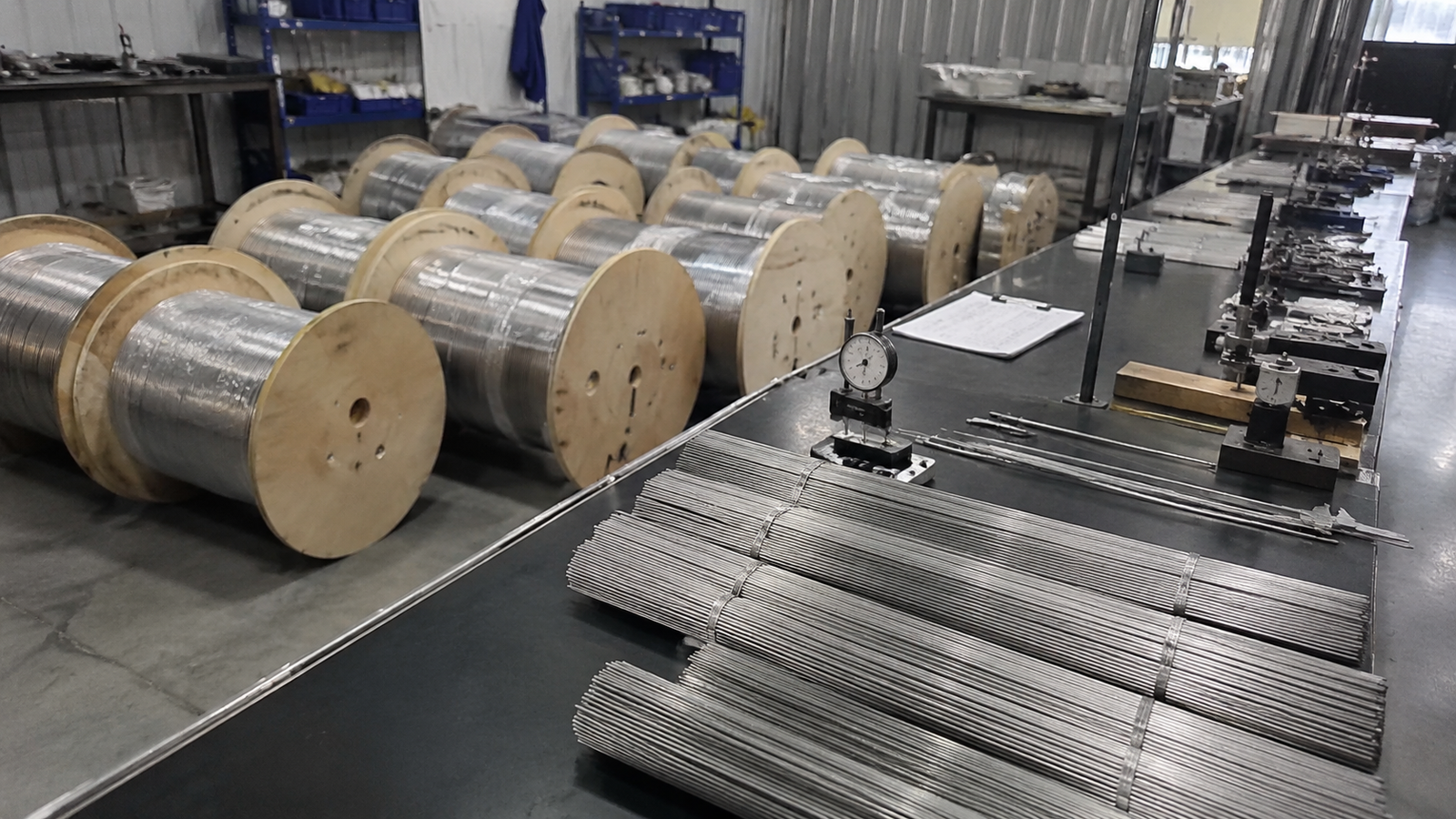
The correct procurement question is not simply:
“Can you supply an Inconel or Hastelloy capillary tube?”
It is:
“Can the supplier manufacture and verify this exact alloy, condition, internal diameter, wall, length, surface, flow characteristic, and inspection requirement using a process that remains consistent across the full production lot?”
This guide explains how industrial buyers can answer that question before production begins.
Capillary Tube Is a Functional Description, Not a Complete Specification
Unlike some pressure pipe and heat-exchanger tube products, there is no universal industrial boundary that defines every capillary tube by one maximum OD or ID.
One supplier may describe a 1.0 mm OD tube as capillary tubing, while another may use the same term for a larger small-bore tube with a relatively narrow internal passage.
The purchase order should therefore avoid relying on the word capillary as the dimensional definition.
A complete dimensional description should include
| Dimensional Item | Required Definition | Why It Matters |
|---|---|---|
| Outside diameter | Nominal OD and tolerance | Controls fitting, routing and assembly |
| Inside diameter | Nominal ID and tolerance | Controls flow, response time and blockage risk |
| Wall thickness | Nominal, minimum or calculated from OD and ID | Controls pressure capacity and formability |
| Wall basis | Minimum wall, average wall or nominal wall | Prevents disagreement over local minimum thickness |
| Ovality | Formula and permitted value | Affects fittings, flow path and pressure response |
| Eccentricity | Measurement and acceptance method | Controls local minimum wall and bore centering |
| Straightness | Measurement length and permitted deviation | Important for automated assembly |
| Length | Straight length, coil length or cut length | Affects pressure drop and installation |
| Cut tolerance | Positive, negative or bilateral | Important for sensor and manifold assembly |
| End condition | Square cut, deburred, chamfered or formed | Prevents blockage and fitting damage |
| Coil diameter | Minimum and maximum coil size | Influences residual curvature and shipping |
| Number of joints | Joint-free length or permitted welds | Affects reliability and traceability |
A specification such as OD 1.6 mm × wall 0.25 mm does not fully define the ID tolerance unless OD and wall tolerances, eccentricity, and measurement method are also stated.
Start With the Intended Function
The application should be defined by what the capillary tube must do, not only by the industry in which it will be used.
| Functional Role | Key Performance Requirement |
|---|---|
| Flow restriction | Stable ID and predictable pressure drop |
| Pressure sensing | Low internal volume, leak tightness and response stability |
| Impulse line | Pressure containment, cleanliness and low blockage risk |
| Chemical injection | Corrosion resistance, pressure capacity and bore patency |
| Sample transfer | Surface compatibility, low contamination and controlled residence volume |
| Thermocouple sheath | Temperature resistance, insulation compatibility and closed-end integrity |
| Sensor protection | Corrosion resistance, wall consistency and mechanical protection |
| Hydraulic control | Pressure fatigue, cleanliness and connection reliability |
| Gas delivery | Leak tightness, cleanliness and internal-surface compatibility |
| Instrument connection | Dimensional fit, bendability and traceable material |
| Microreactor or laboratory line | Chemical compatibility, small internal volume and cleaning |
| Medical-device component | Final-device performance, surface, fatigue and regulatory assessment |
The phrase industrial capillary tube does not reveal which of these requirements controls the design.
Collect Complete Operating Data
A material should not be selected until both normal and abnormal conditions are known.
Minimum application data
| Application Input | Information to Confirm | Possible Effect |
|---|---|---|
| Fluid or gas | Complete chemical identity | Determines alloy compatibility |
| Concentration | Minimum, normal and maximum | Corrosion may change with concentration |
| Temperature | Minimum, normal and maximum | Affects corrosion, strength and flow |
| Pressure | Operating, design and transient | Affects wall and test requirements |
| External pressure | Vacuum or surrounding pressure | May control collapse |
| Flow rate | Minimum and maximum | Affects pressure drop and residence time |
| Flow regime | Liquid, gas, two-phase or pulsed | Changes hydraulic behaviour |
| Solids | Particle size and concentration | Creates blockage or erosion risk |
| Chlorides | Normal and abnormal level | Relevant to localized corrosion |
| Sulfides and H₂S | Concentration and partial pressure | May trigger sour-service requirements |
| pH | Full expected range | Affects passive-film stability |
| Oxygen | Aerated, deaerated or variable | Changes corrosion behaviour |
| Cleaning chemistry | Acids, alkalis, solvents or steam | May be more severe than normal service |
| Sterilization | Temperature and method | Affects surface and mechanical state |
| Thermal cycling | Frequency and range | Influences fatigue and joints |
| Pressure cycling | Frequency and amplitude | Influences fatigue life |
| Vibration | Source and expected level | Affects fretting and fatigue |
| Required life | Hours, cycles or years | Supports material and testing decisions |
| Failure consequence | Leakage, contamination or safety effect | Controls inspection rigor |
“Acid service,” “seawater service,” or “high-temperature sensor” is not enough information for final alloy selection.
Why Internal Diameter Is Often the Most Critical Dimension
For many capillary applications, OD determines assembly fit, but ID determines function.
ID can control:
- Flow rate
- Pressure drop
- Fluid response time
- Delivered chemical quantity
- Sample volume
- Sensor damping
- Blockage sensitivity
- Cleaning feasibility
- Wire or sensing-element fit
Under ideal laminar flow of a Newtonian fluid in a straight circular tube, the simplified Hagen–Poiseuille relationship indicates that flow is highly sensitive to internal diameter.
For fixed pressure difference, viscosity and length:
Flow rate is proportional to ID⁴
This simplified relationship does not apply unchanged to every gas, turbulent flow, compressible fluid, two-phase stream, entrance condition or non-Newtonian fluid.
However, it demonstrates why a seemingly small ID variation can produce a much larger flow difference.
Simplified sensitivity illustration
| ID Change | Approximate Relative Flow Change Under Ideal Laminar Conditions |
|---|---|
| ID increases by 1% | Flow increases by about 4% |
| ID decreases by 1% | Flow decreases by about 4% |
| ID increases by 2% | Flow increases by about 8% |
| ID decreases by 2% | Flow decreases by about 8% |
| ID increases by 5% | Flow increases by about 22% |
| ID decreases by 5% | Flow decreases by about 19% |
These values are simplified mathematical comparisons, not production acceptance limits.
The buyer should establish acceptable ID variation from the actual system model, not from a generic percentage.
Nominal ID Does Not Prove Full-Length ID Uniformity
Measuring only the two cut ends can miss internal variation.
Possible ID variations include:
- Gradual taper
- Local necking
- Periodic variation from drawing or straightening
- Internal weld reinforcement
- Local debris
- Lubricant residue
- Burr intrusion
- Partial collapse after coiling
- Local ovality
- Internal scale
A historical NIST study on internal-diameter uniformity of metallic capillary tubes demonstrated that internal variations can occur along the length and that end measurements alone may be insufficient for precision flow applications.
Possible ID verification methods
| Method | Possible Use | Important Limitation |
|---|---|---|
| Pin or plug gauge | Short straight accessible bores | Limited length and discrete sizes |
| Air gauging | Comparative ID measurement | Requires calibration and controlled geometry |
| Flow test | Functional comparison | Influenced by fluid, temperature, length and end condition |
| Pressure-drop test | Functional consistency | Requires controlled test setup |
| Mass-flow calibration | High-accuracy functional verification | More complex and application-specific |
| X-ray or computed tomography | Internal geometry and blockage | Cost, resolution and length limitations |
| Destructive sectioning | Direct local measurement | Sample-based and destroys product |
| Optical bore inspection | Accessible larger microbores | Limited for very small or long IDs |
| Ultrasonic wall measurement | Wall and eccentricity in suitable dimensions | May be difficult at extremely small sizes |
| Weight-based indirect check | Process monitoring | Cannot identify local ID variation |
The RFQ should identify whether the acceptance requirement is based on dimensional measurement, functional flow, or both.
Wall Thickness, Eccentricity, and Concentricity
A capillary tube can meet its average wall requirement while containing a locally thin region.
Wall eccentricity means that the inside bore is not centered within the OD.
This affects:
- Local pressure stress
- Burst margin
- Bending behaviour
- Collapse resistance
- Fitting engagement
- Fatigue resistance
- Flow-axis alignment
- Minimum remaining wall after forming
Dimensional relationships
For a perfectly concentric tube:
Nominal wall = (OD − ID) / 2
Real tubing may not be perfectly concentric.
The buyer should therefore distinguish between:
- Calculated nominal wall
- Measured average wall
- Local minimum wall
- Maximum wall
- Wall eccentricity
- Bore offset
Eccentricity questions
| Question | Why It Matters |
|---|---|
| Is minimum wall specified? | Protects pressure and forming margin |
| Is wall measured at multiple positions? | Detects nonuniformity |
| Is eccentricity reported? | Identifies bore offset |
| Is OD roundness controlled? | Prevents misleading wall calculations |
| Is the measurement destructive or nondestructive? | Determines coverage |
| Is the requirement applied before or after bending? | Forming can change local wall |
| Is measurement uncertainty reported? | Important near tight limits |
A supplier should not claim micron-level wall control without identifying the measurement method, sampling plan, and uncertainty.
Pressure Capacity Must Be Calculated, Not Assumed From Small Size
A small outside diameter does not automatically make a capillary tube suitable for high pressure.
Internal-pressure capacity depends on:
- OD
- Minimum wall
- Material strength
- Temperature
- Supplied condition
- Manufacturing tolerance
- Eccentricity
- Surface defects
- Connections
- Fatigue cycles
- Applicable design code
- Inspection quality
External-pressure or vacuum resistance depends on a different set of conditions, including:
- OD-to-wall ratio
- Ovality
- Straightness
- Unsupported length
- Material modulus
- Boundary conditions
- External pressure
- Temperature
- Initial imperfections
| Loading Condition | Main Concern |
|---|---|
| Internal pressure | Circumferential tensile stress |
| External pressure | Ovalization and collapse |
| Pressure pulsation | Fatigue |
| Rapid pressure change | Transient loading |
| High temperature and pressure | Reduced strength or creep |
| Fitting compression | Local wall deformation |
| Bending plus pressure | Combined stress |
| Vibration plus pressure | Fatigue and fretting |
Pressure-test requirements should come from the applicable product standard, design basis, and purchaser specification.
A generic statement such as “tested to 1.5 times working pressure” is not a complete procurement requirement.
Select the Alloy Family Before the Exact Grade
Nickel-containing alloys solve different problems depending on their principal alloying elements.
The Nickel Institute overview of nickel-alloy families distinguishes nickel-copper, nickel-chromium, nickel-molybdenum, nickel-chromium-molybdenum, and other groups.
| Alloy Family | Possible Strength | Important Limitation |
|---|---|---|
| Nickel-copper | Useful in selected reducing and marine environments | Oxidizing contaminants and service-specific limits |
| Nickel-chromium | Oxidation and high-temperature corrosion resistance | May not provide the strongest localized-corrosion resistance |
| Nickel-molybdenum | Resistance in selected reducing acids | Oxidizing species can change performance |
| Nickel-chromium-molybdenum | Broad localized-corrosion resistance in many environments | Cost, availability and environment-specific limits |
| Nickel-iron-chromium | High-temperature and selected chemical service | Grade-specific phase and temperature requirements |
| Nickel-titanium | Superelastic or shape-memory behaviour | Processing-sensitive and not equivalent to conventional corrosion-resistant nickel alloys |
| Precipitation-hardened nickel alloy | High strength | Forming, heat treatment and corrosion state require control |
The family is a screening tool, not final approval.
Screening Common Nickel Alloy Candidates
The following table identifies possible starting points only.
It does not replace environment-specific corrosion data, pressure design, fatigue analysis, or regulatory review.
| Alloy | UNS | Possible Screening Context | Important Questions |
|---|---|---|---|
| Alloy 400 | N04400 | Selected marine, alkaline and reducing environments | Aeration, flow, sulfides, oxidizing contaminants and galvanic coupling |
| Alloy 600 | N06600 | Selected high-temperature and corrosion applications | Water chemistry, SCC mechanism, temperature and product condition |
| Alloy 601 | N06601 | High-temperature oxidation and carburization screening | Exact atmosphere, thermal cycling and fabrication |
| Alloy 625 | N06625 | Chloride-bearing, mixed-corrosion and strength-demanding applications | Specific chemistry, temperature, annealed condition, fatigue and standard |
| Alloy 800 | N08800 | Selected high-temperature and process applications | Whether 800, 800H or 800HT is actually required |
| Alloy 800H | N08810 | Elevated-temperature creep-strength applications | Grain, heat treatment, code data and availability in small sizes |
| Alloy 800HT | N08811 | Higher-temperature creep applications within defined code limits | Exact standard, condition and manufacturing route |
| Alloy 825 | N08825 | Selected acid, chloride and reducing/oxidizing mixed services | Acid concentration, temperature, contaminants and heat treatment |
| Alloy C-276 | N10276 | Severe mixed chemical environments | Whether actual chemistry supports this grade over another Ni-Cr-Mo alloy |
| Alloy C-22 | N06022 | Selected oxidizing and chloride-bearing environments | Comparative corrosion data, product availability and weld condition |
| Nickel 200/201 | N02200/N02201 | Selected caustic and reducing service | Temperature, sulfur compounds, carbon level and design code |
| Alloy 718 | N07718 | High-strength applications requiring qualified heat treatment | Corrosion environment, ageing condition, fatigue and small-tube availability |
The material should always be specified by:
- Formal alloy designation
- UNS number
- Product standard
- Supplied condition
- Seamless or welded form
- Required mechanical range
Alloy 625 Is Not One Universal Product Condition
ASTM B444-23 covers cold-worked seamless Alloy 625 pipe and tube and distinguishes annealed Grade 1 and solution-annealed Grade 2 conditions.
The standard also includes requirements for mechanical properties, hydrostatic testing, and nondestructive electric examination. ASTM B444-23
A buyer specifying only Alloy 625 capillary tube may still leave unanswered:
- Which heat-treatment condition?
- Which product standard?
- What actual yield-strength range?
- Is the tube intended for subsequent forming?
- Is high-temperature creep relevant?
- Is the product seamless or welded?
- Which NDT is required?
- Does the standard cover the ordered dimensions?
- Are additional ID tolerances required?
The exact condition can materially affect drawing, coiling, bending and fatigue behaviour.
C-276 and C-22 Require the Correct Product Standard
ASTM B622-23 covers a broad group of seamless nickel and nickel-cobalt alloy pipe and tube, including UNS N10276 and UNS N06022.
The materials covered by this standard are supplied in the specified condition and are subject to product requirements defined by the standard. ASTM B622
However, ASTM compliance does not prove suitability for a particular:
- Acid mixture
- Chloride level
- Oxidizing contaminant
- Temperature
- Pressure
- Flow rate
- Cleaning chemical
- Vapour phase
- Crevice geometry
C-276 should not be described as universally resistant to every aggressive chemical.
C-22 should not be selected merely because it has higher chromium than another alloy.
The final choice should be based on relevant corrosion data and the complete service environment.
Alloy 600 and 601 Are Not Interchangeable
ASTM B167-23 covers several nickel-chromium and nickel-chromium-iron alloys in seamless pipe and tube form.
The standard includes Alloy 600 and Alloy 601 among its covered materials. ASTM B167-23
| Selection Topic | Alloy 600 | Alloy 601 |
|---|---|---|
| Primary screening emphasis | Selected high-temperature and corrosion service | High-temperature oxidation and related environments |
| Aluminium addition | Lower | Used to support protective oxide formation |
| Exact suitability | Environment-specific | Environment-specific |
| Capillary availability | Must be confirmed | Must be confirmed |
| Product condition | Must follow the applicable standard | Must follow the applicable standard |
| Joining and forming | Procedure-specific | Procedure-specific |
The purchaser should not substitute one for the other without technical approval.
Alloy 800, 800H, and 800HT Must Be Named Correctly
These grades have related chemistry but different controlled requirements and intended design uses.
A purchase order stating only Alloy 800 family creates a significant risk.
| Grade | UNS | Main Procurement Concern |
|---|---|---|
| Alloy 800 | N08800 | General corrosion and elevated-temperature service within its applicable limits |
| Alloy 800H | N08810 | Controlled carbon and grain-related requirements for creep service |
| Alloy 800HT | N08811 | Additional chemistry controls and high-temperature creep application |
The buyer should confirm:
- Correct UNS number
- Correct ASTM or ASME product standard
- Required grain condition
- Heat-treatment condition
- Design temperature
- Allowable-stress data
- Small-diameter manufacturing feasibility
A capillary supplier should not relabel Alloy 800 as 800H or 800HT based only on approximate chemistry.
Nitinol Is a Separate Material-Selection Problem
Nickel-titanium shape-memory alloy should not be grouped casually with Alloy 625, Alloy 600, C-276, or Alloy 400.
Nitinol performance can depend on:
- Nickel-titanium composition
- Transformation temperatures
- Cold work
- Heat treatment
- Shape setting
- Surface oxide
- Electropolishing
- Fatigue history
- Final geometry
- Sterilization
- Nickel release
- Final-device loading
The FDA guidance for medical devices containing Nitinol emphasizes the processing sensitivity and unique thermomechanical behaviour of this material.
Medical-use corrections
The following assumptions are unsafe:
- Any nickel alloy is automatically biocompatible.
- An industrial MTC proves medical-device suitability.
- A tube grade used in chemical service can automatically be used in a patient-contacting device.
- Raw-tube corrosion data proves final-device corrosion performance.
- A Nitinol tube is acceptable without evaluating final heat treatment and shape setting.
Medical applications may require:
- Final-device biocompatibility evaluation
- Corrosion testing
- Nickel-release assessment
- Fatigue and fracture testing
- Surface characterization
- Particulate evaluation
- Sterilization validation
- Manufacturing-process validation
- Regulatory documentation
The final device—not only the original tube—must be evaluated.
Industrial Application Screening
Nickel alloy capillary tubes may be considered in applications where common materials do not satisfy the full combination of chemistry, temperature, pressure, precision, or cleanliness.
| Industry | Possible Use | Critical Selection Questions |
|---|---|---|
| Chemical processing | Sample, injection or sensor line | Exact chemical, concentration, temperature and cleaning |
| Petrochemical | Instrument and analyser tubing | Sulfur species, temperature, pressure and vibration |
| Oil and gas | Small-bore chemical injection or sensing line | H₂S, chloride, pressure cycling and applicable sour-service standard |
| Offshore | Instrumentation and control functions | Seawater exposure, galvanic coupling and external pressure |
| Aerospace | Sensor, instrumentation or high-temperature small-bore line | Approved aerospace specification, fatigue and weight trade-off |
| Power generation | Monitoring, sampling or thermocouple sheath | Water chemistry, temperature and cyclic operation |
| Furnace and heat treatment | Thermocouple or atmosphere-sampling sheath | Oxidation, carburization and thermal cycling |
| Analytical instrumentation | Corrosive or high-temperature sample transfer | Adsorption, surface, ID uniformity and dead volume |
| Semiconductor processing | Controlled gas or chemical delivery | Purity, particles, surface and outgassing |
| Laboratory systems | Microreactor or high-pressure test line | Chemical compatibility, flow calibration and connection safety |
| Medical devices | Specialized Nitinol or qualified metallic component | Final-device regulation, fatigue and biocompatibility |
| Nuclear applications | Instrumentation and sampling | Approved material, traceability, cleanliness and nuclear QA |
These are potential application categories, not automatic alloy recommendations.
Chromatography and Analytical Applications Need Additional Caution
Many capillary chromatography systems use fused silica, stainless steel, coated tubing, or other specialized materials.
Nickel alloy tubing may be considered when the system involves:
- Corrosive samples
- High temperature
- Reactive gases
- Elevated pressure
- Mechanical protection
- A requirement to avoid a specific stainless-steel interaction
However, material selection must also consider:
- Sample adsorption
- Catalytic activity
- Surface oxide
- Dead volume
- Internal roughness
- Cleaning
- Detector compatibility
- Connection design
A corrosion-resistant alloy is not automatically chemically inert for every analytical compound.
Sour Oil and Gas Service Requires Formal Review
A generic statement such as nickel alloy for sour gas is incomplete.
Where applicable, NACE MR0175/ISO 15156 supports the selection and qualification of cracking-resistant metallic materials for H₂S-containing oil and gas production environments.
The review may need to consider:
- H₂S partial pressure
- pH
- Chlorides
- Temperature
- Elemental sulfur
- Material condition
- Hardness
- Cold work
- Applied stress
- Residual stress
- Coupling with other materials
The term sour-service capillary tube should not be accepted without the environmental definition and applicable material limits.
Manufacturing Route Strongly Influences the Finished Tube
Nickel alloy capillary tubing is commonly produced through multiple reductions and intermediate processing steps.
Possible operations include:
- Tube hollow preparation
- Pilgering
- Cold drawing
- Plug drawing
- Mandrel drawing
- Sinking
- Intermediate annealing
- Final annealing
- Straightening
- Coiling
- Pickling
- Bright annealing
- Polishing
- Cleaning
- End cutting
Each operation can influence final dimensions and properties.
| Manufacturing Variable | Possible Effect |
|---|---|
| Reduction per pass | Surface, dimensional control and work hardening |
| Mandrel or plug condition | ID finish and size |
| Die alignment | Eccentricity and ovality |
| Intermediate annealing | Ductility and grain condition |
| Final annealing | Strength, residual stress and formability |
| Straightening | Residual stress and periodic dimensional variation |
| Coiling | Residual curvature and local ovality |
| Lubricant | Surface cleanliness and bore contamination |
| Pickling | Surface oxide and dimensional loss |
| Bright annealing atmosphere | Surface condition and contamination |
| Cut-off method | Burr and bore blockage |
| Tool wear | Dimensional drift across a production lot |
The supplier should define which operations are performed in-house and which are subcontracted.
Annealed and Cold-Worked Conditions Are Not Equivalent
Cold working generally increases strength and hardness while reducing remaining ductility.
Annealing can restore ductility and alter grain structure, but it may lower strength and change surface condition.
| Requirement | More Annealed Condition May Support | More Cold-Worked Condition May Support |
|---|---|---|
| Tight bending | Greater formability | Greater crack risk if deformation margin is low |
| Pressure strength | May require more wall | Higher strength may be available |
| Fatigue | Depends on surface, stress and alloy | Higher strength does not automatically mean better fatigue |
| Flaring | Often easier | May be restricted |
| Straightness | Process-dependent | Process-dependent |
| Dimensional stability | Process-dependent | Residual stress may be higher |
| Tube expansion | More deformation capacity may be available | Higher force may be required |
| Surface hardness | Lower | Higher |
| Subsequent heat treatment | May be unnecessary | May change final properties substantially |
The RFQ should not use vague wording such as:
- Soft
- Half hard
- Hard
- Fully annealed
unless the condition is linked to a recognized standard or agreed property range.
Seamless and Welded Capillary Tubes Should Be Evaluated Neutrally
Seamless construction eliminates a longitudinal weld, but it does not eliminate all quality risks.
Welded construction includes a weld seam, but it is not automatically unsuitable.
| Topic | Seamless Tube | Welded Tube |
|---|---|---|
| Longitudinal weld | None | Present |
| Possible dimensional issue | Eccentricity and drawing variation | Weld geometry and forming variation |
| ID condition | Influenced by drawing route | Influenced by weld bead and subsequent working |
| NDT focus | Base material and dimensions | Base material plus weld seam |
| Small-size production | Process capability must be confirmed | Weldability and reduction route must be confirmed |
| Forming | Depends on condition and wall | Depends on condition, weld and weld orientation |
| Product standard | Alloy-specific seamless standard | Alloy-specific welded standard |
| Acceptance | Based on complete specification | Based on complete specification |
ASTM B704-23 covers welded tubes in selected alloys including UNS N06625 and N08825 for boiler, heat-exchanger, and condenser applications.
ASTM B751-21 provides general requirements for listed longitudinally welded nickel and nickel-alloy tubular products.
Neither standard automatically covers every commercial capillary dimension or application.
Verify the Product Standard Before Ordering
ASTM B829 is a general-requirements standard, not a substitute for the specific alloy product standard.
| Product Example | Possible ASTM Product Standard | Important Scope Check |
|---|---|---|
| Seamless Alloy 600/601 tube | ASTM B167 | Alloy, condition and dimensional scope |
| Seamless Alloy 625 tube | ASTM B444 | Grade 1 or Grade 2 condition |
| Seamless C-276/C-22 tube | ASTM B622 | Alloy list, condition and size scope |
| Seamless Alloy 400 tube | ASTM B165 | Condition and dimensional requirements |
| Heat-exchanger tube in listed alloys | ASTM B163 | Alloy list, service and small-diameter provisions |
| Welded Alloy 625/825 tube | ASTM B704 | Product scope and weld requirements |
| General seamless requirements | ASTM B829 | Only with the particular product standard |
| General welded-tube requirements | ASTM B751 | Only with the particular welded product standard |
Standard review checklist
- [ ] Correct standard title
- [ ] Correct edition
- [ ] Correct alloy
- [ ] Correct UNS number
- [ ] Seamless or welded form
- [ ] Required condition
- [ ] Dimensional range
- [ ] Light-wall provisions
- [ ] Hydrostatic-test requirement
- [ ] NDT requirement
- [ ] Mechanical tests
- [ ] Chemical requirements
- [ ] Permitted tolerances
- [ ] Supplementary requirements
- [ ] Conflict hierarchy
A supplier should not write ASTM B829 capillary tube without also identifying the particular alloy product standard.
Standard Tolerances May Not Be Sufficient for Precision Flow
A product can comply with its ASTM standard and still fail to meet an instrument's flow or assembly requirement.
This is not necessarily a material nonconformance.
It may mean the project requires tighter supplementary tolerances.
Supplementary tolerance areas
| Characteristic | Why a Project May Need Tighter Control |
|---|---|
| ID | Flow or response accuracy |
| Full-length ID variation | Functional consistency |
| Minimum wall | Pressure or bending |
| Eccentricity | Uniform stress and fitting |
| OD | Connector fit |
| Ovality | Sealing and flow |
| Straightness | Automated insertion |
| Cut length | Manifold assembly |
| Burr | Blockage risk |
| Internal roughness | Cleanliness or sample interaction |
| Coil memory | Installation |
| End roundness | Fitting engagement |
Tighter tolerances should be based on functional need and verified manufacturing capability.
An unnecessarily tight tolerance may increase:
- Scrap
- Cost
- Lead time
- Inspection burden
- Minimum order quantity
Surface Finish Must Be Specified Separately
A material grade does not define the final OD and ID surface.
Possible delivered surfaces include:
- Cold drawn
- Pickled
- Bright annealed
- Mechanically polished
- Electropolished
- Chemically cleaned
- Passivated where applicable
- Custom cleaned and capped
Surface characteristics to define
| Surface Requirement | Possible Acceptance Method |
|---|---|
| No cracks or laps | Visual and appropriate NDT |
| Scratch limit | Depth or visual reference |
| ID roughness | Profilometry or agreed method |
| OD roughness | Profilometry |
| Oxide condition | Visual or surface specification |
| Iron contamination | Project-specific test |
| Oil residue | Solvent extraction or cleanliness test |
| Particles | Flush test or particle count |
| Moisture | Dryness or dew-point test |
| Burr-free ends | Visual or magnified inspection |
| Electropolish removal | Process record and dimensional check |
“Smooth surface” is not a measurable requirement.
The RFQ should state the required parameter, method, sampling, and limit.
Cleanliness and Bore Patency Are Critical
A very small ID can be blocked or restricted by contamination that would be insignificant in a larger tube.
Potential contaminants include:
- Drawing lubricant
- Metal particles
- Pickling residue
- Oxide
- Fibres
- Packaging debris
- Cutting burrs
- Moisture
- Cleaning-agent residue
- Polishing compound
Bore-patency verification
| Method | Possible Purpose |
|---|---|
| Air-flow check | Confirms open bore and gross consistency |
| Liquid-flow check | Functional verification |
| Pressure-decay test | Detects blockage or leakage depending on setup |
| Wire or gauge passage | Confirms minimum accessible ID in suitable tubes |
| Flush inspection | Identifies particles and residue |
| Borescope | Visual inspection where size permits |
| X-ray or CT | Internal restriction assessment |
| Weight comparison | Process monitoring only |
| End microscopy | Burr and deformation check |
A supplier report stating cleaned should identify the process and acceptance criteria.
Testing Must Match the Defect and the Tube Size
No inspection method is equally suitable for all capillary dimensions.
| Inspection Method | Possible Purpose | Limitation to Review |
|---|---|---|
| Visual examination | OD defects and workmanship | Limited internal access |
| Dimensional inspection | OD, ID, wall, length and ovality | Sampling and measurement uncertainty |
| Eddy-current testing | Conductive-material discontinuities | Coil and reference-standard suitability for very small sizes |
| Ultrasonic testing | Wall and internal discontinuities | Coupling, curvature and thin-wall resolution |
| Hydrostatic testing | Pressure integrity | Test fixture and small internal volume |
| Pneumatic testing | Leakage or pressure verification | Stored-energy safety |
| Helium leak testing | Sensitive leak detection | Does not replace structural proof where required |
| Dye penetrant | Surface-breaking defects | Cleaning and surface access |
| Radiography | Internal geometry or selected defects | Resolution, cost and orientation |
| CT scanning | ID, eccentricity and blockage | Cost and production coverage |
| Metallography | Grain and wall examination | Destructive sampling |
| Hardness testing | Condition and consistency | Difficult on very thin walls |
| Tensile testing | Mechanical properties | Small-size specimen limitations |
| Flow testing | Functional ID consistency | Fluid and setup must be controlled |
The supplier should demonstrate that the selected method can achieve the required sensitivity for the actual OD, wall and alloy.
“100% NDT” is incomplete unless the method, calibration, coverage, sensitivity and acceptance criteria are specified.
Functional Testing May Be More Useful Than a Dimension Alone
For a flow-restriction or dosing application, a functional flow test may better represent performance than an isolated ID measurement.
A functional test should define:
- Test fluid or gas
- Fluid purity
- Inlet pressure
- Outlet pressure
- Temperature
- Tube length
- End fittings
- Stabilization time
- Measurement instrument
- Calibration
- Allowed flow range
- Correction method
- Leak acceptance
| Test Variable | Why It Must Be Controlled |
|---|---|
| Temperature | Changes viscosity and gas density |
| Length | Directly affects pressure drop |
| ID | Strongly affects flow |
| End condition | Adds entrance or fitting losses |
| Pressure | Defines driving force |
| Gas compressibility | Changes calculation |
| Fluid contamination | Can alter flow or block the tube |
| Instrument uncertainty | May exceed the tolerance being measured |
A project should not specify both an extremely narrow ID tolerance and flow tolerance without confirming that they are compatible and measurable.
First-Article Inspection Reduces Production Risk
A first article is useful for a new combination of:
- Alloy
- OD
- ID
- Wall
- Length
- Condition
- Surface
- Coil form
- Heat treatment
- Flow requirement
Possible first-article package
| First-Article Item | Suggested Evidence |
|---|---|
| Material identity | MTC/MTR and PMI where required |
| OD | Measurement report |
| ID | Measurement or functional report |
| Wall | Minimum and multiple-position results |
| Eccentricity | Cross-section or suitable NDT |
| Ovality | Defined calculation |
| Straightness | Fixture or measurement report |
| Length | Final dimensional report |
| Surface | Photographs and roughness data |
| Cleanliness | Flush, residue or particle result |
| Bore patency | Flow or passage test |
| Pressure integrity | Applicable test report |
| NDT | Method and calibration record |
| Heat treatment | Furnace chart and condition |
| Packaging | Trial packing photographs |
Approval of a first article does not eliminate production inspection.
It establishes a verified manufacturing route and acceptance reference.
Supplier Process Capability Matters More Than a Sample Alone
A supplier may produce one acceptable sample but lack the process control to repeat it over a full lot.
Capability evidence
| Capability Area | Evidence to Request |
|---|---|
| Similar dimensions | Previous production range |
| Similar alloy | Material-specific experience |
| Drawing equipment | Machine and tooling range |
| Annealing | Furnace control and atmosphere |
| ID control | Measurement and process data |
| Eccentricity control | Cross-section or NDT data |
| Surface control | Process and roughness records |
| Cleaning | Procedure and acceptance |
| Flow calibration | Test setup and uncertainty |
| NDT | Equipment and reference standards |
| Traceability | Traveler and heat-control system |
| Calibration | Valid instrument records |
| Change control | Written notification procedure |
| Packaging | Coil and straight-tube protection |
Process capability may be expressed through:
- Historical range
- Control charts
- Cp or Cpk where appropriate
- Yield data
- First-article results
- Lot inspection results
A capability index should not be accepted without understanding sample size, distribution, measurement uncertainty and process stability.
ISO 9001 Does Not Replace Product Verification
ISO guidance for the supply chain explains that ISO 9001 does not define the technical requirements of the goods being purchased.
A valid ISO 9001 certificate may support evaluation of:
- Document control
- Calibration
- Corrective action
- Traceability processes
- Supplier control
- Nonconformance handling
- Process monitoring
It does not by itself prove:
- Correct alloy
- Correct ID
- Minimum wall
- Full-length ID uniformity
- Surface cleanliness
- Pressure integrity
- Flow consistency
- Medical suitability
- Sour-service compliance
The buyer must still issue measurable product requirements.
Material Certificates Must Be Cross-Checked
An MTC or MTR should be linked to the physical material.
Document review table
| Certificate Field | Required Verification |
|---|---|
| Producing mill | Actual tube manufacturer or upstream mill |
| Alloy | Formal designation |
| UNS number | Correct identity |
| Product standard | Correct standard and edition |
| Heat number | Matches physical marking |
| Lot number | Matches manufacturing and inspection records |
| Product form | Seamless or welded |
| Supplied condition | Annealed, solution annealed or cold worked |
| Chemistry | Meets standard and supplementary limits |
| Tensile strength | Meets specified range |
| Yield strength | Meets specified range |
| Elongation | Meets specified requirement |
| Hardness | Correct method where required |
| Heat treatment | Correct cycle or condition |
| NDT | Method, extent and result |
| Pressure test | Requirement and result |
| Dimensions | Matches purchase description |
| Certificate type | Matches contractual requirement |
Documents the MTC does not normally replace
- Detailed dimensional report
- ID uniformity report
- Surface-roughness report
- Flow-calibration report
- Cleanliness certificate
- First-article report
- Packaging inspection
- Application qualification
- Final-device regulatory documentation
Traceability Must Survive Cutting and Recoiling
Capillary tubing may be supplied in long coils and cut into many short pieces.
Traceability can be lost during:
- Cutting
- Straightening
- Recoiling
- Cleaning
- Heat treatment
- Sorting
- Rework
- Packaging
Possible traceability methods include:
- Heat-separated coils
- Individual tags
- Lot travellers
- Barcode labels
- Cut maps
- Container-level identification
- Furnace-load records
- Inspection-lot records
Direct marking on a tiny tube may be impractical or may damage the surface.
The purchase order should therefore define whether traceability is required at:
- Individual piece level
- Coil level
- Bundle level
- Sealed package level
- Production-lot level
Delivery Form Affects Installation and Quality
| Delivery Form | Possible Advantage | Possible Risk |
|---|---|---|
| Straight length | Easier dimensional and straightness inspection | Length limitation and more joints |
| Large coil | Long joint-free length | Coil memory and handling |
| Small coil | Compact shipping | Greater residual curvature |
| Layer-wound spool | Controlled payout | Spool contamination or crushing |
| Cut pieces | Ready for assembly | More end handling and traceability complexity |
| Preformed component | Reduced customer fabrication | Geometry and forming qualification required |
Coil requirements may include
- Coil inside diameter
- Coil outside diameter
- Maximum coil height
- Winding direction
- Number of coil ends
- Joint-free length
- Maximum number of coils per heat
- Tie material
- Protective wrapping
- Payout direction
A supplier should not substitute straight tubing with coiled tubing or change coil diameter without approval when straightness or automated feeding is critical.
Packaging Must Prevent Blockage and Deformation
Small-bore tubing can be damaged by packaging practices that are acceptable for larger tubes.
Packaging risks
- Tube flattening under straps
- Kinked coil
- Crushed ends
- Open ends collecting debris
- Moisture ingress
- Cross-contamination
- Labels detached from coils
- Different heats mixed
- Excessive coil memory
- Forklift penetration
- Tube rubbing
Recommended controls
| Packaging Item | Control |
|---|---|
| Ends | Clean caps or sealed bags where specified |
| Coil support | Rigid spool or supported coil |
| Straps | Non-crushing tension |
| Separators | Clean, non-contaminating material |
| Moisture | Barrier and drying where required |
| Identification | Heat, lot, size and length |
| Lifting | Defined lifting points |
| Stack height | Limited to prevent deformation |
| Cleanliness | Packaging compatible with service |
| Photographs | Record before closure and loading |
The packaging requirement should match the product's surface and cleanliness class.
Change Control Is Essential
A supplier should notify the buyer before changing an essential manufacturing variable.
Changes that may affect capillary tube performance
- Raw-material mill
- Heat-treatment source
- Drawing machine
- Die or mandrel design
- Reduction schedule
- Lubricant
- Annealing atmosphere
- Straightening method
- Coil diameter
- Cleaning chemistry
- NDT equipment
- ID measurement method
- Subcontractor
- Packaging method
The purchase specification should identify which changes require:
- Notification
- Written approval
- New first article
- Additional testing
- Requalification
A dimensional certificate from an earlier process route may not validate a changed manufacturing route.
What Buyers Should Include in the RFQ
| RFQ Category | Required Information |
|---|---|
| Application | Functional use of the tube |
| Fluid | Full chemistry and phase |
| Temperature | Operating, design and transient |
| Pressure | Internal, external and cyclic |
| Alloy | Formal grade and UNS number |
| Product standard | ASTM, ASME, AMS, EN or project specification |
| Construction | Seamless or welded |
| Condition | Annealed, solution annealed, cold worked or other |
| OD | Nominal and tolerance |
| ID | Nominal, tolerance and uniformity requirement |
| Wall | Nominal, average or minimum |
| Eccentricity | Formula and limit |
| Ovality | Formula and limit |
| Length | Straight, coil or cut length |
| Straightness | Measurement and tolerance |
| End condition | Cut, deburred, capped or formed |
| Surface | OD and ID finish |
| Roughness | Parameter, method and limit |
| Cleanliness | Oil, particles, moisture and residue |
| Bore patency | Flow, passage or other method |
| Pressure test | Method, pressure and acceptance |
| NDT | Method, extent and calibration |
| Functional test | Fluid, pressure, temperature and flow range |
| Mechanical tests | Tensile, hardness or project-specific |
| Heat treatment | Required condition and records |
| Documentation | MTC, EN 10204 type and inspection reports |
| Traceability | Piece, coil, package or lot level |
| First article | Quantity and approval documents |
| Third-party inspection | Hold and witness points |
| Packing | Coil, spool, caps and moisture protection |
| Quantity | Total length, pieces and spare quantity |
| Delivery | Schedule and destination |
Common Procurement Mistakes
| Mistake | Why It Is Risky | Better Approach |
|---|---|---|
| Specifying only “nickel alloy capillary tube” | Alloy and dimensions remain undefined | Add UNS, standard, condition, OD, ID and wall |
| Selecting by trade name | Similar trade families include different grades | Use formal alloy and UNS |
| Measuring only tube ends | Full-length ID variation remains unknown | Add functional or full-length verification |
| Controlling OD but not ID | Flow may vary significantly | Specify both |
| Calculating wall from nominal dimensions only | Local minimum wall may be lower | Specify minimum wall and eccentricity |
| Assuming smaller OD means higher pressure capacity | Wall, defects and condition still control | Perform code-based assessment |
| Requiring micron tolerance without measurement plan | Requirement may be unverifiable | Define method and uncertainty |
| Assuming C-276 fits every acid | Actual environment may differ | Use relevant corrosion data |
| Assuming Alloy 625 is always annealed the same way | B444 includes different conditions | State the required grade and condition |
| Treating Nitinol like conventional nickel alloy | Thermomechanical behaviour differs | Use Nitinol-specific qualification |
| Calling any medical nickel alloy biocompatible | Final-device processing matters | Perform regulatory and biological evaluation |
| Requiring generic 100% NDT | Method may not suit the size | Define method, sensitivity and reference |
| Accepting ISO 9001 as product approval | It does not define product characteristics | Review product-specific evidence |
| Accepting MTC without physical traceability | Certificate may not match shipment | Cross-check heat and lot markings |
| Skipping first article | A full lot may repeat one process error | Approve representative samples |
| Ignoring cleaning | Small bore may be partially blocked | Add cleanliness and patency requirements |
| Ignoring coil diameter | Installation and straightness may be affected | Specify delivery form |
| Selecting on unit price alone | Failure, rework and calibration costs are excluded | Compare lifecycle and process risk |
Incoming Inspection Checklist
Documentation
- [ ] Correct alloy designation
- [ ] Correct UNS number
- [ ] Correct product standard
- [ ] Correct standard edition
- [ ] Seamless or welded form confirmed
- [ ] Supplied condition confirmed
- [ ] Heat and lot numbers match
- [ ] Chemistry reviewed
- [ ] Mechanical properties reviewed
- [ ] Heat treatment reviewed
- [ ] NDT reports reviewed
- [ ] Pressure-test report reviewed
- [ ] Dimensional report reviewed
- [ ] Flow or patency report reviewed where required
- [ ] Cleanliness certificate reviewed
- [ ] First-article approval confirmed
Physical checks
- [ ] Quantity or total length confirmed
- [ ] Coil or bundle identification matches
- [ ] OD measured
- [ ] ID verified by the agreed method
- [ ] Minimum wall checked
- [ ] Eccentricity reviewed
- [ ] Ovality reviewed
- [ ] Length checked
- [ ] Straightness or coil condition checked
- [ ] Ends inspected for burrs or collapse
- [ ] OD surface inspected
- [ ] Bore patency confirmed
- [ ] Caps or seals intact
- [ ] Moisture or contamination checked
- [ ] Packaging damage documented
Technical release
- [ ] Material is suitable for the application
- [ ] Product standard covers the ordered form
- [ ] Tolerances meet the functional requirement
- [ ] Inspection method is technically suitable
- [ ] No unapproved substitution occurred
- [ ] Deviations are formally closed
- [ ] Product is released for fabrication or installation
Frequently Asked Questions
What size is considered a nickel alloy capillary tube?
There is no single universal industrial size boundary. The purchase specification should define the exact OD, ID, wall thickness, tolerances, length and delivery form rather than relying on the word capillary.
Is ID or OD more important?
It depends on the function. OD often controls fitting and assembly, while ID can control flow, pressure drop, response time and blockage. Many applications require tight control of both.
Why is full-length ID uniformity important?
A local restriction or gradual ID change can alter flow and pressure response even when both tube ends meet the nominal ID requirement. Precision flow systems may therefore require functional testing or additional internal measurement.
Can the wall thickness be calculated from OD and ID?
A nominal wall can be calculated as (OD − ID) / 2, but this assumes perfect concentricity. Actual minimum wall may be lower because of eccentricity, ovality and manufacturing variation.
Is seamless tubing always more accurate than welded tubing?
No. Seamless tubing eliminates a longitudinal weld but may still have eccentricity, ovality or drawing variation. Welded tubing requires weld control but may be suitable when manufactured and tested to the correct standard.
Is Alloy 625 always the best general-purpose nickel alloy capillary tube?
No. Alloy 625 is a strong candidate in many demanding environments, but C-276, C-22, Alloy 400, Alloy 600, Alloy 825 or another material may be more appropriate depending on chemistry, temperature, pressure and fabrication.
Is Hastelloy C-276 resistant to every acid?
No. Its performance depends on the acid, concentration, temperature, impurities, oxygen, velocity and phase. Relevant corrosion data are still required.
Can Monel 400 always be used in seawater?
No. Aeration, velocity, stagnant conditions, sulfides, galvanic coupling and temperature can influence performance. The exact seawater system must be reviewed.
Are nickel alloy capillary tubes commonly used for all medical needles?
No. Medical needle materials and final-device requirements vary. Conventional corrosion-resistant nickel alloys should not be assumed suitable for patient contact without final-device evaluation.
Is Nitinol simply another corrosion-resistant nickel alloy?
No. Nitinol is a nickel-titanium material with shape-memory or superelastic behaviour. Its performance is highly sensitive to processing, heat treatment, surface condition and final-device geometry.
Does ISO 9001 certification prove that the tubing is high quality?
No. It indicates that the organization operates a quality-management system. Product-specific alloy, dimensions, surface, cleanliness, testing and traceability must still be verified.
Is an MTR enough to approve the tubing?
No. An MTR generally verifies heat-specific material data. It does not necessarily prove ID uniformity, surface roughness, cleanliness, flow performance, final cut quality or application suitability.
Which NDT method is best for capillary tubing?
There is no universally best method. Suitability depends on alloy, OD, wall, defect type, required sensitivity and reference-standard feasibility. Very small dimensions may require a combination of methods.
Should every capillary tube be flow tested?
Not every application requires it. Flow testing is particularly useful when the tube acts as a restriction, dosing element, calibrated passage or precision sensor line.
Can custom tolerances always be achieved?
Custom tolerances may be possible, but feasibility depends on alloy, size, length, manufacturing route, quantity and measurement capability. The supplier should demonstrate capability before mass production.
Why is a first article important?
It confirms that the proposed manufacturing route can achieve the required ID, wall, surface, cleanliness and functional performance before the entire order is produced.
How should capillary tubes be packaged?
Packaging should prevent kinking, crushing, end damage, contamination, moisture and heat-number loss. Coil size, spool type, end caps and identification should be defined in the RFQ.
Conclusion
Selecting nickel alloy capillary tubes for industrial use requires more than comparing alloy data sheets.
A technically complete decision should address:
- Functional purpose
- Fluid or gas chemistry
- Temperature and pressure
- Internal and external loading
- Corrosion and cracking mechanisms
- Alloy and UNS designation
- Product standard
- Seamless or welded form
- Annealed or cold-worked condition
- OD and full-length ID control
- Minimum wall and eccentricity
- Ovality and straightness
- Pressure drop and flow consistency
- Surface finish
- Cleanliness and bore patency
- Pressure and NDT requirements
- Functional testing
- Medical or sour-service qualification
- Material certificates and traceability
- Supplier process capability
- First-article approval
- Change control
- Packaging and delivery form
For buyers, the most effective approach is to translate the application's performance requirements into measurable tube characteristics before requesting a final quotation.
For manufacturers, the appropriate approach is to confirm whether the alloy, dimensions, condition, testing and measurement methods are technically feasible, then preserve the approved process through controlled production and traceable inspection records.
Clear technical agreement before manufacturing reduces the risk of discovering inconsistent flow, restricted bores, insufficient wall, surface contamination, unsuitable material condition or incomplete documentation after the tubes have already been produced and delivered.